Heathkit HERO 2000 (ET-19) · Volume 2
Architecture — One 8088 Master, Many Slaves
2.1 The defining idea
The single architectural fact that separates the HERO 2000 from every Heathkit
robot before it is that no one processor does everything. The HERO 1 and the
HERO Jr each ran a single Motorola 6808 — an 8-bit microprocessor that, in
between executing the user’s program, also had to scan the keypad, time the
sonar, drive the motors, and feed the speech synthesizer, all by hand and all in
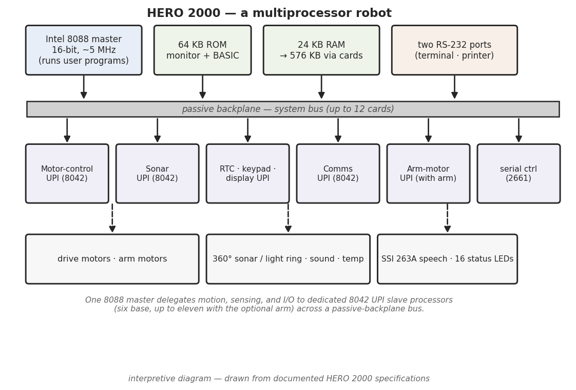
software. The HERO 2000 instead splits that work across a small fleet of
processors: an Intel 8088 acts as the master and runs the user’s program,
while a set of dedicated Intel 8042 UPI slave processors each take charge of
one real-time subsystem (hero.dsavage.net HERO 2000 spec sheet; theoldrobots.com;
Wikipedia, “HERO (robot)”). This is a multiprocessor design — a small
distributed computer on wheels rather than one CPU doing time-shared duty — and
it is the headline of the whole machine.
The payoff of that split is the theme of this volume. When a separate processor is continuously watching the wheel motors, or continuously stepping the sonar through its bearings, the master 8088 is freed from those tight real-time loops. It can run BASIC, talk to a terminal, or compute the next move while the slaves hold the subsystems steady underneath it. The same restructuring is what let the HERO 2000 carry a 360-degree sensor ring, an expandable card cage, and a text-to-speech subsystem without the master collapsing under interrupt load — each of those lives behind its own processor.
2.2 The Intel 8088 master
2.2.1 What it is
The HERO 2000’s main processor is an Intel 8088 (HERO 2000 spec sheet; theoldrobots; Wikipedia). The 8088 is a 16-bit processor internally — 16-bit registers and arithmetic — that talks to memory over an 8-bit external data bus, the same compromise Intel struck so the part could drive cheap 8-bit support chips and memories. That lineage matters for placing the HERO 2000: the 8088 is the processor of the IBM PC and PC/XT, and of Heath/Zenith’s own Z-151 desktop computer of the same era (selectric.org). The robot is, at its core, PC-class silicon on a mobile chassis — a sharp contrast with the 1 MHz 8-bit 6808 of the HERO 1 and HERO Jr.
2.2.2 Clock speed — a flagged conflict
The record disagrees on how fast the master runs. The transcribed factory spec
sheet (hero.dsavage.net) gives the 8088 as running at roughly 5 MHz,
which is the figure this deep dive carries as primary. One secondary source
instead reports 4.77 MHz — the canonical IBM PC clock — most likely by
analogy to the PC/XT rather than from a HERO measurement. Both readings are
recorded here; the 5 MHz of the spec sheet is treated as the better-supported
value, and the ET-19 Technical Manual is the primary a reader should consult
for the definitive crystal frequency. The two figures are close enough that
nothing in the robot’s behaviour turns on which is exact, but they are not
silently reconciled.
Table 1 — Clock speed — a flagged conflict
| Reading | Source | Note |
|---|---|---|
| ~5 MHz | HERO 2000 spec sheet (hero.dsavage.net) | Carried as primary here |
| 4.77 MHz | One secondary | The IBM PC/XT clock; likely by analogy |
2.2.3 What the master actually does
The 8088 is the part of the machine the user programs against. It runs the monitor and HERO 2000 BASIC out of ROM, executes the user’s application, and coordinates the slaves — issuing high-level commands (“rotate to this bearing”, “drive forward”, “say this text”) and reading back results, rather than managing the moment-to-moment electrical detail itself (HERO 2000 spec sheet; inferred from the master/slave division of labour). The memory it addresses — 24 KB of RAM expandable to 576 KB, and 64 KB of ROM — is the subject of Vol. 3; the languages it runs are the subject of Vol. 8. The exact bus widths, address decoding, and the map by which the master reaches each slave are documented in the ET-19 Technical Manual and are deliberately not reconstructed here.
2.3 The 8042 UPI slave processors
2.3.1 One processor per subsystem
Beneath the master sits a layer of Intel 8042 Universal Peripheral Interface processors — the slaves (HERO 2000 spec sheet). The 8042 is itself a complete single-chip microcontroller from the MCS-48 family: it carries its own CPU, its own program ROM, its own RAM, a timer, and I/O ports, and it is designed specifically to sit on a host’s bus and offload a peripheral task. (The same UPI family is the part famously used as the keyboard controller in the IBM PC/AT.) In the HERO 2000, each 8042 is dedicated to a single subsystem and runs the tight, timing-critical loop for that subsystem on its own, reporting to the 8088 over the backplane.
The spec sheet documents one slave for each of the robot’s real-time domains (HERO 2000 spec sheet):
Table 2 — (HERO 2000 spec sheet)
| Slave (8042 UPI) | Subsystem it owns | Covered in |
|---|---|---|
| Motor-control UPI | The two drive servo-motors; differential steering | Vol. 4 |
| Sonar UPI | The 24-bearing sonar/light ranging ring | Vol. 5 |
| RTC / keypad / display UPI | Real-time clock, keypad input, display output | Vol. 8 |
| Communications UPI | The serial/console communications path | Vol. 8 |
| Arm-motor UPI (with optional arm) | The multi-jointed arm’s motors | Vol. 6 |
Alongside the UPIs, the communications path also carries a 2661 — a programmable serial communications controller (an EPCI/UART-class part) — handling the framing and timing of the RS-232 serial link so neither the master nor the communications UPI has to bit-bang it (HERO 2000 spec sheet). The 2661 is a fixed-function serial controller rather than a programmable slave like the 8042s, but it belongs to the same delegation story: a dedicated chip taking a real-time chore off the master.
2.3.2 The “Z-80” claim — flagged and rejected
One secondary account describes the HERO 2000’s slave processors as Z-80s. That reading is not supported by the spec sheet, which identifies the slaves as Intel 8042 UPIs — a different part from a different family (Intel’s MCS-48 microcontroller line, not Zilog’s Z-80 CPU line). This deep dive gates the slave identity to the 8042 UPI of the spec sheet and records the “Z-80” description only to flag it as contradicted: a Z-80 is a general-purpose 8-bit CPU that would need its own external ROM, RAM, and glue, whereas the 8042 is a self-contained single-chip peripheral controller — exactly the kind of part a one-per-subsystem slave layer would use. The “Z-80” claim should be treated as an error in the secondary record unless the ET-19 Technical Manual says otherwise.
2.4 How many processors
Counting the master and the slaves gives the figure that makes the HERO 2000 remarkable for its day. The spec sheet’s per-subsystem slave list — motor, sonar, RTC/keypad/display, communications — plus the master comes to a base of about six processors, and fitting the optional arm adds its arm-motor UPI and brings the total up to eleven (HERO 2000 spec sheet; Wikipedia). Wikipedia states the count directly, describing the machine as carrying “eleven 8-bit peripheral microprocessors” at its fullest configuration (Wikipedia, “HERO (robot)”).
A note on how to read that number: Wikipedia’s “eleven 8-bit peripheral microprocessors” counts the peripheral processors and is the maximum, with the arm fitted; this deep dive’s “6 base, up to 11 with the arm” rolls the master 8088 and the base slaves together at the low end and reaches the same eleven at the high end. The precise allocation of which subsystem owns which slot, and any additional UPIs beyond the documented set, is left to the ET-19 Technical Manual and is not invented here. What is certain across the sources is the shape of the thing: a single 16-bit master orchestrating roughly half a dozen to a dozen 8-bit processors working in parallel.
Table 3 — How many processors
| Configuration | Approx. processor count | Source |
|---|---|---|
| Base (no arm) | ~6 (8088 master + documented 8042 slaves) | spec sheet |
| With optional arm | up to 11 | Wikipedia (“eleven … peripheral microprocessors”) |
2.5 The passive backplane
2.5.1 A shared bus, not a fixed board
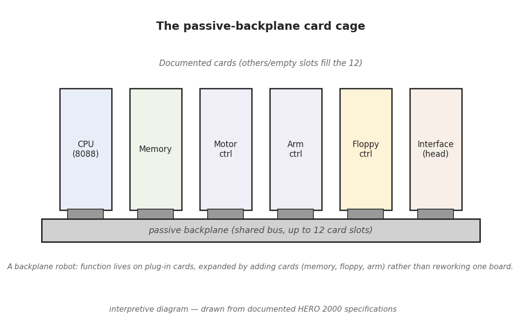
The processors and memory do not sit on one big soldered motherboard. The HERO 2000 is built around a passive backplane — a board carrying only the bus wiring and the card connectors, with no active logic of its own — into which the functional cards plug (theoldrobots; selectric.org). The master CPU, the memory, the motor controller, the arm controller, the floppy controller, and the head-interface card are each a separate card that shares the common bus through the backplane, the same way the expansion cards of a desktop PC share the bus through its slots. The backplane is documented as accepting up to 12 cards (theoldrobots; Selectric).
This is the physical embodiment of the multiprocessor idea. Because the bus is passive and the functions are carded, the architecture is modular and expandable: memory grows by adding memory cards, the arm is enabled by adding its controller card, and floppy storage appears by adding the floppy controller card — none of which is possible on the fixed, soldered single-board designs of the HERO 1 and HERO Jr. The card set and the 12-slot cage are the subject of Vol. 3; this volume’s concern is simply that the backplane is the shared medium over which the 8088 master reaches every slave and every memory bank.
2.5.2 Why a backplane suits a multiprocessor robot
The passive-backplane-plus-cards layout and the master/slave processor split reinforce each other. Each subsystem can be its own card carrying its own 8042 slave, debugged and serviced as a unit; the master reaches each card over the same bus; and the configuration the buyer actually owns — arm or no arm, base RAM or expanded, floppy or not — is just a question of which cards are seated. A robot built this way can be repaired card-by-card and grown over its life, which is exactly the posture of a machine sold as an advanced educational and automation-training platform rather than a sealed appliance. The exact bus signals on the backplane, the card-edge pinouts, and the address ranges each card answers to are documented in the ET-19 Technical Manual and are not reconstructed in this deep dive.
2.6 The contrast with the single-processor HEROs
It is worth stating the generational break plainly, because it is the whole point
of the architecture. The HERO 1 (ET-18) and the HERO Jr (RT-1) were each built on
a single Motorola 6808 running at about 1 MHz, with all subsystem work
time-shared in that one processor’s software (HERO 1 and HERO Jr deep dives;
_shared/comparison.md). Every sonar ping, motor step, and speech phoneme on
those machines competed for the same CPU’s attention. The HERO 2000 replaces that
single 8-bit CPU with a 16-bit 8088 master plus a layer of 8042 slaves, so the
real-time subsystems run concurrently and independently and the master is left to
do the high-level work. The table below places the three machines side by side.
Table 4 — The contrast with the single-processor HEROs
| HERO 1 (ET-18) | HERO Jr (RT-1) | HERO 2000 (ET-19) | |
|---|---|---|---|
| Processing model | Single CPU, time-shared | Single CPU, time-shared | Multiprocessor: master + slaves |
| Master CPU | Motorola 6808 @ ~1 MHz | Motorola 6808 @ ~1 MHz | Intel 8088 @ ~5 MHz (one source 4.77 MHz) |
| Slave processors | None | None | Intel 8042 UPIs, 1 per subsystem |
| Processor count | 1 | 1 | ~6 base, up to 11 with arm |
| Construction | Single board | Single board | Passive backplane, up to 12 cards |
| Serial controller | — | — | 2661 on the comms path |
The remaining volumes open each of these subsystems in turn behind its slave: Vol. 3 the memory and the 12-slot card cage; Vol. 4 the dual-servo drive behind the motor-control UPI; Vol. 5 the 360-degree ring behind the sonar UPI; Vol. 6 the optional arm and the eleventh processor; Vol. 7 the text-to-speech subsystem; and Vol. 8 the I/O and communications path behind the communications UPI and the 2661. The definitive bus, address, and slot detail this volume defers belongs to the factory ET-19 Technical Manual.
Comments (0)