Heathkit HERO 2000 (ET-19) · Volume 9
Acquisition, Restoration & Interfacing Today
9.1 Buying an ET-19 today
The HERO 2000 reaches the collector market as one of two factory variants: the ET-19, sold assembled, and the ET-19W, the kit a builder soldered up at home (HERO 2000 spec sheet; Vol. 1). Both are the same machine once finished, but the distinction matters to a buyer for two reasons. A kit-built unit reflects the care of whoever assembled it three or four decades ago — workmanship varies — while an assembled ET-19 left the factory to a uniform standard. And because the HERO 2000 was the most expensive HERO at roughly $2,000 as a kit and $4,500 assembled (robotworkshop) and sold in comparatively small numbers — about 3,000 units over a line discontinued in 1995 (Wikipedia) — surviving examples are scarce relative to the cheaper, more numerous HERO 1 and HERO Jr.
What separates a parts-grade shell from a complete, valuable machine is the optional equipment. Three items in particular drive completeness and therefore value:
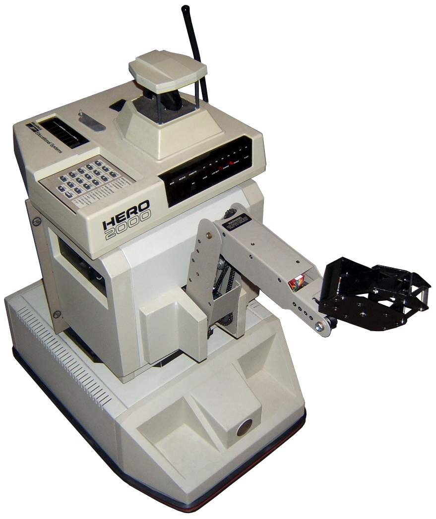
- The optional arm. The multi-jointed arm and gripper are an add-on, not part of the base robot, and they carry the 11th processor and the Arm-Controller card with them (Vol. 6). A HERO 2000 with its arm present and intact is a materially more complete machine than a torso-only unit.
- The remote console keyboard. The detachable console/keyboard over which the robot was programmed (Vol. 8) is easily separated from the robot and easily lost.
- The docking charger. The mains charger and its docking cradle (Vol. 8; Selectric) are the means of keeping the machine alive, and a missing charger is a missing subsystem.
A representative reference point for a complete unit is the Bonhams listing of a c.1986 HERO 2000 offered with its arm, remote keyboard, and charger together (Bonhams) — the configuration a collector would treat as whole. The presence or absence of those three items is the first thing to establish about any unit on offer. No reliable price series exists in the sources gathered here, so price guidance is left unclaimed; condition and completeness, not a published figure, govern value.
9.2 Documentation — the restorer’s primaries
The authoritative references for a restoration are the factory ET-19 Technical
Manual and the ET-19 Programming Manual. The Computer History Museum catalogs
the manual set, and copies circulate on the collector market (CHM; sourcing notes).
Unlike the HERO 1 and HERO Jr — whose factory manuals are freely downloadable from
archive.org — a clean free PDF of the ET-19 Technical Manual is not confirmed
available in the sources gathered here; the manual is cited as the primary a
restorer should consult and, where a scan is not in hand, deeper technical details
in this series are gated instead to the transcribed factory spec sheet at
hero.dsavage.net, which is the most chip-level source available (sourcing notes;
Vol. 1).
The practical consequence for a restorer is that the Technical Manual is the document to acquire alongside the robot. The ROM helps: the HERO 2000’s 64 KB ROM carries demo, diagnostic, and sensor-adjustment routines in addition to the monitor and HERO 2000 BASIC (spec sheet; Vol. 3), so a working machine can be exercised and its sensors checked from on-board firmware before any external documentation is consulted.
9.3 Aging concerns
The specifics of how any individual unit has aged cannot be asserted from the record, and nothing below should be read as a measured failure rate or a quoted part. The notes here are qualitative and attributed: they identify the subsystems most worth inspecting and cite the one firsthand restoration in the sources — the Selectric writeup (selectric.org/hero2000) — for the failures it actually encountered.
9.3.1 The 12 V sealed-lead-acid battery
The battery is the single subsystem most likely to need replacement. The HERO 2000 runs from a 12 V sealed-lead-acid (SLA) pack, and the record carries an unresolved conflict over its capacity and endurance: the factory spec sheet gives 12 V, 14 Ah, with roughly 4–6 hours of active operation, while theoldrobots describes a single 24 Ah battery lasting “up to six days” (spec sheet; theoldrobots). The two readings are most plausibly reconciled as active runtime (~4–6 h) versus standby endurance (days), but the 14 Ah-versus-24 Ah capacity figure itself is a genuine discrepancy between the sources and is flagged rather than resolved here. Either way, a sealed-lead-acid cell that has sat for decades will almost certainly have lost capacity or failed outright, and replacement is the expected restoration step.
SLA replacement is also the most hazardous routine task on the machine, and
_shared/safety.md must be consulted before any battery work. Its battery section
notes that old SLA cells can leak acid and can deliver very high short-circuit
current — a dead short across the pack can weld tools and start fires — so the
pack must be fused, never shorted at the terminals, and leaking cells disposed of
properly (_shared/safety.md). The same page directs that charging be done on
a non-flammable surface, ventilated, and attended (_shared/safety.md).
9.3.2 The arm’s cable-and-pulley mechanics
The optional arm is driven through a system of cables and pulleys, and it is the
mechanism the firsthand restoration found most fragile. During the Selectric
restoration a wrist cable broke and a dislodged torso cable had to be
re-seated (Selectric). Those two failures are attributed to that single account
and should not be generalized into a pattern, but they flag where to look first on
an arm-equipped unit: the cable runs and their pulleys, particularly at the wrist
and through the torso. The arm’s documented joint ranges (shoulder 0–120°, elbow
0–180°, wrist pivot −179° to +180°) are covered in Vol. 6; any cable, tension, or
pulley specifics beyond what Selectric reports are left unclaimed. The safety page’s
mechanical cautions apply during any arm work — the Heathkit arms move with real
force, joints and the gripper are pinch and crush points, and the machine
should be powered down before reaching into the mechanism (_shared/safety.md).
9.3.3 The card-cage connectors
The HERO 2000 is built around a passive backplane carrying up to 12 plug-in
cards — CPU, memory, motor controller, arm controller, floppy controller, and the
head interface among them (Selectric; Vol. 2, Vol. 3). A multi-card cage of this age
is worth inspecting at its edge-connector contacts, where decades of oxidation
can produce intermittent faults that present as subsystem failures rather than
connector problems. The safety page’s general guidance to photograph and label
connector orientation and wire colors before disassembly applies directly to a
card cage, where reseating a card in the wrong slot or orientation is a real risk
(_shared/safety.md). Specific slot assignments are not reconstructed here and are
deferred to the ET-19 Technical Manual (Vol. 3).
9.3.4 The docking charger
The robot is kept charged through a 120 VAC charger and a docking cradle with
angled rails that guide the machine into contact (spec sheet; Selectric). The
charger is mains-powered, which brings it under the safety page’s electrical
cautions: treat any opened line-voltage wiring as live, unplug before working
inside and verify with a meter, and replace cracked line cords and failed strain
reliefs (_shared/safety.md). The same section warns that aging filter
capacitors in a decades-old supply can dry out or short and should be inspected
for bulging or leakage and reformed or replaced before full power is applied
(_shared/safety.md). The internal charger circuit is not documented in the sources
here and is not described in detail.
9.4 Safety — before any battery or charger work
Because two of the most likely restoration tasks — the SLA pack and the mains
charger — are also the two most hazardous, this volume defers explicitly to
_shared/safety.md rather than restating its rules piecemeal. Its Batteries
section governs the SLA pack (leak and short-circuit hazard, fuse the pack, charge
ventilated and attended) and its Electrical section governs the charger (treat
mains wiring as live, meter before touching, inspect aging electrolytics), while its
Mechanical section covers the arm and drive (pinch and crush points, power down
before reaching in). Any restoration or interfacing work on a HERO 2000 should begin
there.
9.5 Modern interfacing
The HERO 2000 is straightforward to connect to a modern computer because its programming interface is ordinary serial. The machine carries two RS-232C serial ports, wired as DCE — one intended for a terminal, one for a printer — running at baud rates up to 38,400 (spec sheet; Vol. 8). That is the same interface a period terminal used to program the robot, and it bridges trivially to a present-day PC through a USB-to-serial adapter: the adapter presents a virtual COM port to the host, and a terminal program at a matching baud rate talks to the robot’s monitor and HERO 2000 BASIC over the terminal port exactly as a 1986 terminal would have. The DCE wiring of the robot’s ports (Vol. 8) determines whether a straight or crossover cable is needed against a given adapter, and the exact pinout is the detail to confirm against the ET-19 Technical Manual before wiring a cable; it is not reconstructed here.
This serial path is the supported, documented route to driving a HERO 2000 from modern equipment, and for most restorers it is sufficient — a working machine, a USB-serial adapter, and a terminal emulator are enough to reach the on-board BASIC and the diagnostic routines. Deeper or undocumented modifications — replacing the battery chemistry, substituting modern storage for the floppy controller, adapting the radio link, or any reverse-engineering of the card bus — are beyond what the sources here document, and this volume makes no claim about how such changes behave or whether they are advisable. They are left explicitly unclaimed.
9.6 What remains unclaimed
Consistent with the no-fabrication rule, several acquisition-relevant specifics are left open rather than invented: current market prices and any failure-rate figures (no reliable series exists in the sources); the battery’s true capacity, where the record itself conflicts (14 Ah per the spec sheet versus 24 Ah per theoldrobots); the internal design of the charger; the card-cage slot assignments (deferred to the ET-19 Technical Manual); and the behavior of any undocumented modification. Where this volume cites the Selectric restoration, the failures described are that single account’s and are attributed accordingly, not generalized into a pattern.
Comments (0)