RoboDog · Volume 10
Vol 10: Power, Thermal, Weatherproofing & All-Season Operation
Power, thermal, and weatherproofing systems are the cross-cutting substrate that determines whether the RoboDog patrol program operates for a few tens of minutes on a dry floor or sustains year-round all-weather missions across rough outdoor terrain. Build 1 confronts this reality directly: its 20–35 minute runtime on a 3S LiPo pack imposes a hard mission ceiling that neither gait optimization nor software tuning can extend past the battery chemistry. Build 3 closes that gap through a full-system redesign — an 888 Wh 12S pack, three power rails derived from the 44.4 V traction bus, autonomous return-to-dock, IP67 sealing throughout, and a heated battery bay for sub-zero operation. This volume treats each of these systems in depth: the energy budget and runtime arithmetic, battery chemistry and BMS, voltage architecture, charging and the auto-dock cycle, the sealing-versus-cooling tension at the heart of thermal management, cold-weather derating and its countermeasures, IP sealing from the standard’s definitions through the implementation, traction for snow and ice, and how each system escalates across the three build tiers.
10.1 Energy Budget
The energy budget begins at the actuator level and works outward. Every joint in the robot converts electrical energy to mechanical output, with resistive and switching losses at each step. The RoboDog build ladder’s three tiers present fundamentally different electrical systems, and the runtime arithmetic reflects each tier’s component choices.
10.1.1 Power Draw Breakdown
At Build 3 scale (12× CubeMars AK80-64 actuators, Jetson AGX Orin 64GB compute, Livox Mid-360 LiDAR, and ancillary sensors), the per-category power draw during active patrol walking at moderate gait speed is:
- Actuators: 12× AK80-64 at rated 7 A each, 44.4 V nominal bus. Peak actuator draw: 12 × 7 × 44.4 = 3,729 W. At 20–25% average torque loading during a patrol walk (the machine maintains stance rather than climbing stairs for the majority of a patrol cycle), average actuator draw: 746–932 W. [1]
- Compute: Jetson AGX Orin 64GB at 20–60 W configurable TDP; at the autonomy stack’s typical concurrent load (LiDAR-SLAM, object detection, Nav2 path planning), estimated draw: 50–60 W. [2]
- Sensors: Livox Mid-360 at 6.5 W average (14 W cold-weather peak), OAK-D Pro at 7.5 W [24], PureThermal 3 at ~1.5 W (approximate) [25], BMI088 IMU at <0.1 W [26]: sensor subtotal ~16–23 W. [3]
- Housekeeping (MCU, logic, status LEDs): ~5 W.
- Total estimated system average: 820–1,020 W during active patrol, rounded to 850–1,025 W. [1][2][3]
10.1.2 Worked Runtime Estimate (Build 3)
The following calculation uses the Build 3 battery as the primary example. All intermediate values are retained at full precision; the final result is rounded.
Inputs:
Table 1 — Inputs:
| Parameter | Symbol | Value | Source |
|---|---|---|---|
| Pack cell count | — | 12S (series) | [4] |
| Nominal cell voltage | V_cell | 3.7 V | Li-polymer chemistry |
| Total nominal voltage | V_bus | 44.4 V | 12 × 3.7 |
| Pack capacity | C | 20,000 mAh (20 Ah) | [4] |
| Nominal energy | E_nom | 888 Wh | V_bus × C = 44.4 × 20 |
| Usable DoD | — | 85% | Standard Li-polymer practice [31] |
| Usable energy | E_use | 755 Wh | 888 × 0.85 |
| Average system power, low | P_low | 850 W | Lower-bound active patrol estimate |
| Average system power, high | P_high | 1,025 W | Upper-bound active patrol estimate |
| Midpoint power | P_mid | 937 W | (850 + 1,025) / 2 |
Calculation:
Runtime at low-power bound: E_use / P_low = 755 / 850 = 0.889 h = 53.3 min
Runtime at high-power bound: E_use / P_high = 755 / 1,025 = 0.737 h = 44.2 min
Result: 44–53 minutes of active patrol before the 20% state-of-charge (SOC) return threshold triggers the auto-dock sequence. [4] The robot does not run to depletion; the return-to-dock threshold preserves 20% SOC (≈ 178 Wh, ≈ 11–12 min of reserve) for the dock approach and charging initiation.
Cold-weather modifier: At −20°C ambient with the PTC heater maintaining a battery surface temperature of approximately 10°C, cell capacity is estimated at 80–85% of nominal (15–20% derating at 10°C rather than the 40–50% loss at unheated −20°C conditions). [5][6] Usable cold energy: 755 × 0.80 = 604 Wh to 755 × 0.85 = 642 Wh. Cold-weather patrol runtime: 604–642 / 937 = 0.64–0.69 h = 38–41 min before the return threshold. [4] This is slightly higher than the 35–40 min cold-weather estimate from Vol 7 [4], which also accounts for increased cold-weather power draw from Livox self-heating and lubricant drag; the Vol 10 arithmetic uses the nominal 937 W midpoint without those additional loads.
10.1.3 Runtime Comparison Across the Build Ladder
Table 2 — Runtime Comparison Across the Build Ladder
| Build | Battery | Nominal (Wh) | Usable (85% DoD) | Avg. System Power | Estimated Runtime |
|---|---|---|---|---|---|
| Build 1 FDM | 3S 2,200 mAh LiPo [7] | 24.4 Wh | ~16 Wh | ~26–30 W | 20–35 min [7] |
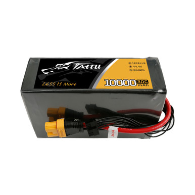
| Build 2 Mid | 12S 10,000 mAh LiPo [8] | 444 Wh | ~377 Wh | ~800–970 W (est.) | ~25–30 min (est.) |
| Build 3 Full | 12S 20,000 mAh LiPo [4] | 888 Wh | ~755 Wh | 850–1,025 W | 44–53 min [4] |
Build 2’s estimated runtime is derived by applying the same average-loading methodology to its 12× AK80-9 actuators. This estimate is materially shorter than the ~90–120 min figure in Vol 6’s battery section [33], which derives runtime from the Vol 4 Tier-2 planning budget of approximately 180–340 W average system draw; this estimate uses a higher average joint-loading assumption scaled from Build 3’s actuator data. The ~3–4× spread between these figures can only be resolved by instrumented BMS telemetry from the running Build 2 prototype (see also the known open item in Vol 11, Synthesis & the Build Roadmap). The mini Pupper 2 reference platform achieves 30–50 min on a 1,000 mAh pack with small custom servos — a useful lower-bound sanity check on the Build 1 figure. [9]
10.1.4 Comparable Commercial Platforms
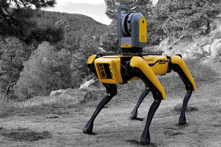
For context, Boston Dynamics Spot achieves approximately 90 minutes of runtime in standard operation at 32.7 kg with IP54 sealing. [10] The Unitree Go2 achieves approximately 1–2 hours with its standard 8,000 mAh / 236.8 Wh battery (third-party estimates; no official Unitree specification publishes a runtime figure), or up to 3–5 hours with the Long Endurance 15,000 mAh / 432 Wh optional pack. [11][12] Neither Spot nor Go2 publishes a cold-weather runtime derating specification; both publish temperature operating ranges (Spot: −20°C to +55°C [10]; Go2: standard pack to −10°C [11]).
10.2 Batteries
10.2.1 Li-Ion vs. LiPo: Chemistry and Form Factor
Both lithium-ion (Li-ion, cylindrical or prismatic cells) and lithium polymer (LiPo, pouch cells) share the same intercalation chemistry: lithium ions shuttle between a graphite anode and a lithium metal oxide cathode through a non-aqueous electrolyte. The practical distinction between them is form factor and electrolyte state.
Li-ion (cylindrical 18650 / 21700 class): Rigid steel-cased cylindrical cells. Energy density approximately 200–265 Wh/kg at the cell level; safer due to rigid case and integrated vent mechanisms; more widely used in consumer electronics and EV packs where pack geometry flexibility is not a priority. [13]
LiPo (lithium polymer, pouch cell): Soft aluminum laminate pouch. Energy density approximately 100–265 Wh/kg depending on cell design; the pouch format allows arbitrary aspect ratios, enabling thin or shaped packs suited to the RoboDog’s spine-mounted battery bay. Discharge rates of 30C or higher are available in hobby-grade cells, supporting the high peak current demanded by QDD actuators at startup. [13] The tradeoff: pouch cells are more mechanically fragile than cylindrical cells and more vulnerable to swelling on overcharge or aging.
For the RoboDog program, LiPo is the specified chemistry at all three tiers because the high C-rate availability (25C at Build 1, 30C at Builds 2 and 3) and form-factor flexibility outweigh the mechanical protection trade-off. The BMS at each tier handles the electrical protection that pouch cells cannot provide mechanically.
10.2.2 Pack Design
A LiPo pack’s voltage is set by cell count in series (S-number). Nominal LiPo cell voltage is 3.6–3.7 V; fully charged is 4.2 V; minimum safe discharge is 3.0–3.5 V depending on cell grade. [13]
- Build 1: 3S pack (11.1 V nominal / 12.6 V fully charged / 9.0 V cutoff). UBEC step-down to servo and compute rails. [7]
- Build 2: 12S pack (44.4 V nominal / 50.4 V fully charged). Feeds AK80-9 actuators rated at 48 V. Buck converter steps down to compute and logic rails. [8]
- Build 3: 12S pack, 20,000 mAh (double Build 2’s capacity). Same 44.4 V bus; AK80-64 rated at 24/48 V. [4]
Cell count in parallel (P-number) increases capacity without changing voltage. The Build 3 pack is effectively a 12S2P configuration (or equivalent large-format single pouch) — doubled capacity at identical bus voltage. [4]
10.2.3 Battery Management System (BMS)
A battery management system monitors and protects the cell pack in real time. For the LiPo packs used across the build ladder, BMS functions include: [23]
- Cell-level voltage monitoring — detects individual cell overcharge (>4.2 V) or over-discharge (<3.0 V) and opens a protection relay before damage occurs.
- Balance charging — during charge, the BMS equalizes cell voltages by shunting or redistributing charge across cells in the series string. Without balancing, individual cell voltages diverge over hundreds of cycles, progressively reducing usable capacity.
- Temperature monitoring — thermistors at multiple points on the pack detect thermal runaway precursor conditions. At sub-zero ambient, the BMS reports cell temperature to the host controller, enabling the PTC heater warm-up sequence.
- State-of-charge estimation — coulomb counting (integrating charge in/out) combined with open-circuit voltage measurement provides the SOC signal that triggers the auto-dock return.
- Short-circuit and overcurrent protection — a MOSFET cutoff switch opens the pack output on any overcurrent event (e.g., a CAN bus fault that forces a single actuator to saturate).
At Build 1 scale, the BMS is integrated into the balance-charger circuit; the pack does not carry on-robot BMS protection beyond the connectors. At Builds 2 and 3, a dedicated on-robot BMS module (or integrated BMS within the Tattu pack’s protective circuitry) is required for the 12S string, where individual cell monitoring is essential to safe operation.
10.3 Voltage Architecture
10.3.1 Power Rails
Three rails serve each build, with increasing rigor at higher tiers.
Build 1 (3S 11.1 V bus):
- Servo rail: 6–6.8 V, via UBEC (universal battery elimination circuit) step-down.
- Compute rail: 5 V / 3 A, via second UBEC. Feeds Raspberry Pi 5.
- No regulated 3.3 V or logic rail is required; the Pi 5 supplies its own 3.3 V from the 5 V input.
Builds 2 and 3 (12S 44.4 V bus):
- Traction rail (44.4 V): Direct from the battery through a fused distribution board and MOSFET soft-start relay. Feeds all twelve actuators through per-actuator blade fuses.
- Compute rail (12 V): High-efficiency synchronous buck converter (>92% efficiency at this voltage ratio, per current synchronous buck designs at 44–48 V to 12 V [32]). Feeds the Jetson module, LiDAR, depth camera, thermal camera, and RTK receiver.
- Logic rail (5 V): Linear or switching regulator from the 12 V compute rail. Feeds the STM32G4 real-time MCU, IMU, USB-CAN adapter, and LED status indicators.
10.3.2 Rail Sequencing and Soft-Start
A lesson carried from Build 1: powering twelve actuators simultaneously before the compute stack is ready induces an inrush current spike that sags the bus voltage and can corrupt the Jetson’s boot sequence. The soft-start relay on the traction rail — a high-side MOSFET opened by a GPIO under STM32G4 firmware control — delays actuator power until the micro-ROS gait node confirms it is ready to receive joint targets. [14] At Build 3, the soft-start relay is rated at 100 A to handle the 19 A peak per AK80-64 at twelve simultaneous actuators. [1]
The boot sequence at Build 3 is:
- Battery connected; 12 V compute rail energizes immediately.
- Jetson AGX Orin and STM32G4 boot; ROS 2 nodes launch (~30 s).
- BMS reports cell temperature to STM32G4. If temperature < 10°C, PTC heater activates; hold actuator power off.
- When battery surface temperature ≥ 10°C (typically 90–180 s in −10°C ambient), STM32G4 closes the soft-start relay.
- Gait controller goes live; patrol sequence begins.
10.3.3 Efficiency and I²R Losses
Moving from the 11.1 V 3S architecture (Build 1) to the 44.4 V 12S architecture (Builds 2 and 3) reduces I²R losses in wiring and connectors by a factor of sixteen for the same delivered power (P = I²R; at 4× higher voltage, current is 4× lower, and I²R loss is 16× lower). At Build 1’s 30 W total draw at 11.1 V, current is approximately 2.7 A. At Build 3’s 937 W at 44.4 V, current is approximately 21 A — substantially higher in absolute terms, but the same mechanical power at 11.1 V would require 84 A, with catastrophic wiring losses and connector failures. The 12S architecture is not optional at QDD actuator power levels; it is the physically correct voltage for this current and power class.
10.4 Charging & Auto-Dock
10.4.1 Bench Charging
All three builds require balance charging: a charger that monitors and equalizes each cell in the series string during the charge cycle. At Build 1 (3S, 2,200 mAh), any B6-class balance charger (approximately US $25) performs this function safely. At Builds 2 and 3 (12S, 10,000–20,000 mAh), a higher-capacity charger is required: the iCharger Duo 300 W class (Build 3) or iCharger 3010B class (Build 2) handles up to 12S at 10–20 A charge current, bringing the 20,000 mAh pack to full charge in approximately 1.5–2.0 hours at 10 A (C/2 rate). [8][4]
10.4.2 Auto-Dock Architecture
Build 3’s autonomous charging dock combines a precision-alignment visual target, contact-pad electrical delivery, and a weatherproof outdoor charger housing. The Unitree Go2’s commercial charging station (available from authorized resellers at approximately €1,200 as of June 2026) demonstrates the production form factor: a low-profile outdoor unit with contact charging at 33.6 V / 9 A, compatible with Go2 models equipped with LiDAR for autonomous approach. [15] An April 2026 field deployment documented autonomous 24/7 patrol-and-return-to-dock operation using this hardware with the Go2 quadruped, confirming that the end-to-end software stack — battery SOC monitoring, return navigation, precision docking, charge-complete re-launch — is achievable on a current consumer quadruped platform. [16]

Boston Dynamics Spot Enterprise includes a commercial docking station for autonomous self-charging at the enterprise tier; the Build 3 dock is designed to provide equivalent function at the builder tier using open-source Nav2 software and owner-fabricated hardware. [10]
Build 3 dock design (from Vol 7): A 250 × 350 × 80 mm weatherproof outdoor station surface-mounted to a concrete pad; two spring-loaded gold-plated contact pads at 48 V / 10 A; an AprilTag fiducial panel at fixed height for sub-50 mm final-approach alignment; a sealed IP65 enclosure housing the 48 V switching power supply. [4] Builds 1 and 2 use manual battery swaps; auto-dock is a Build 3 first.
10.5 Thermal Management
10.5.1 Motor Heating
Brushless DC motors generate heat from two sources: copper losses (I²R in the stator windings) and iron losses (eddy current and hysteresis in the stator laminations). At the AK80-64’s 7 A rated current, copper losses in the stator winding dominate. The FOC driver board and power electronics add additional switching losses. [1]
The AK80-64’s operating temperature range is −20°C to 50°C, measured at the housing. [1] Sustained operation above 48 N·m continuous rated torque (e.g., extended stair-climbing sequences) approaches the thermal limit of the motor winding insulation; the CAN-bus telemetry from each actuator includes motor temperature, and the CHAMP locomotion controller at Build 3 should implement a gait-slowdown or duty-cycle-reduction behavior when any joint exceeds 45°C housing temperature.
At Build 1 (DS3218MG hobby servos), thermal derating is a constant concern: the MG996R class operates near its torque limit during normal walking, dissipating excess energy as heat in the motor core and plastic gearbox housing. This is precisely the mechanism that teaches the Build 1 operator to expect thermal shutdowns after 10–15 minutes of sustained trot — a concrete lesson that motivates the QDD actuator transition at Build 2.
10.5.2 Electronics Cooling — The Sealing-vs-Cooling Tension
The fundamental tension in outdoor electronics design is this: the same sealing that keeps water out also keeps heat in. A sealed enclosure with no thermal path to the outside traps waste heat from the compute stack, BMS, and power converters until the electronics exceed their rated junction temperatures.
For the Jetson AGX Orin 64GB (15–60 W configurable TDP), the developer kit’s standard heatsink + fan assembly provides adequate cooling in open-air bench configurations. In a sealed IP67 enclosure, that fan path is eliminated. The Build 3 solution uses conduction cooling: the Orin module is mounted on a custom aluminum cold plate that conducts heat to the 6061-T6 enclosure walls, which act as a large-surface heat spreader, then radiate and convect to ambient through the external surface of the enclosure. This approach works adequately at 50 W Orin draw; at 60 W sustained, an additional thermal pad between the cold plate and the spine aluminum structure may be required to maintain junction temperatures below the 80°C limit.
At Build 2, the electronics enclosure is IP5X (polycarbonate box with a pressed-fit lid and no O-ring), which provides dust resistance but not immersion resistance. The partial sealing is sufficient for light drizzle, and a small gap in the enclosure lid provides a natural convection path that keeps the Orin NX 16GB below its thermal limit in the 25 W operating regime.
Breathable membranes as a partial solution. GORE Protective Vents use an expanded PTFE (ePTFE) microporous membrane that allows air and gas exchange — maintaining pressure equalization between the sealed enclosure interior and the external environment — while blocking liquid and particulate ingress. [17] Rapidly changing temperature or altitude creates differential pressure across a sealed enclosure; repeated pressure cycling fatigues gaskets and O-rings, eventually degrading the seal. The Gore screw-in vent series maintains IP68-equivalent protection while providing this equalization function. [18] Build 3 specifies one Gore screw-in vent on the spine electronics enclosure to manage thermal expansion during patrol cycles in ambient temperature swings of 40°C or more (e.g., −15°C at night to +25°C at mid-day).
10.6 Cold-Weather Operation
Cold weather imposes three distinct challenges on the RoboDog system: battery capacity loss, lubricant viscosity increase in gearboxes, and condensation management when the machine transitions between cold and warm environments.
10.6.1 Battery Capacity Derating
Lithium polymer cells lose capacity at sub-freezing temperatures because ionic conductivity in the liquid electrolyte decreases and charge-transfer kinetics at the electrode surfaces slow. [5][6] Two independent sources confirm the derating magnitude:
- At 0°C: approximately 20–30% capacity loss (70–80% of rated capacity available). [5][6]
- At −20°C (unheated): approximately 40–50% capacity loss (50–60% of rated capacity available). [5][6] Battery University reports “about 50 percent performance level at −18°C.” [6]
DroneTrust’s published figure of ~80% capacity at 0°C and 50–60% at −20°C [5] sits at the optimistic end of this range; the DroneTrust data aligns with high-quality aerospace-grade cells. Standard hobby-grade LiPo cells (used at all three build tiers) should be budgeted at the 20–30% loss at 0°C and 40–50% loss at −20°C range.
Build 3 countermeasure: A 50 W PTC (positive temperature coefficient) silicone heater pad wrapped around the battery pack, thermostated at 15°C minimum surface temperature. The boot sequence holds actuator power off until the battery reports ≥10°C surface temperature. [4] PTC heaters are inherently self-regulating: their resistance rises as temperature increases, preventing overheating without a separate control loop. At −20°C ambient, pre-heating to 10°C surface temperature takes approximately 90–180 seconds. This reduces effective capacity derating to approximately 15–20%, preserving 80–85% of usable energy — yielding the 38–41 minute cold-weather patrol window noted in the energy budget section above.
Build 1 and Build 2 carry no cold-weather battery management. Build 1 is indoor-only; Build 2 is rated for light weather but not −20°C operation.
10.6.2 Lubricant Viscosity and Gearbox Effects
At sub-zero temperatures, grease viscosity increases, raising static friction (“stiction”) in the AK80-64’s 64:1 planetary gearbox. This has two effects: (a) a higher breakaway torque is required to initiate movement, increasing current draw during the first few gait cycles; and (b) the increased friction elevates gearbox heat dissipation during steady-state walking, which partially counteracts the cold environment. [4]
The AK80-64 is rated to −20°C; CubeMars’ operating temperature specification implies that the factory-specified grease remains within its viscosity range at this temperature. [1] For operation below −20°C (outside the actuator’s rated range), a synthetic low-temperature grease (e.g., Mobilgrease XHP 222 or Nyogel 767A) would be a rebuild maintenance item. At Build 3’s −20°C cold-weather target, the factory grease specification is adequate.
10.6.3 Condensation Management
Condensation occurs when a cold surface (e.g., the electronics enclosure after a night patrol) is brought into a warm, humid indoor environment. Warm air contacts the cold enclosure walls, and water vapor condenses inside if there are any humidity pathways. In a perfectly sealed IP67 enclosure with no breathable membrane, this condensation occurs during the initial cold soak, when warm indoor air was the last air inside before sealing.
The Gore ePTFE membrane vent mitigates this by allowing slow moisture exchange: as the enclosure cools, slight negative pressure draws dry outside air in through the ePTFE membrane, which blocks liquid but allows vapor at very low rates; accumulated moisture vapor escapes when the enclosure warms and interior vapor pressure exceeds ambient. [17][18] Without a vent, a sealed enclosure acts as a moisture trap; over hundreds of patrol cycles and temperature swings, accumulated condensation corrodes PCB traces, connector contacts, and bearing races.
At Builds 1 and 2 (no IP67 sealing), condensation mitigation relies on silica gel desiccant packs inside the electronics enclosure and regular inspection. At Build 3, the Gore vent plus the fully sealed O-ring enclosure handles this systematically.
10.7 IP Sealing
10.7.1 The IP Rating Standard
IEC 60529 defines the International Protection (IP) rating system — a two-digit code specifying an enclosure’s resistance to solid particle and liquid ingress. [19] The first digit rates solid particle protection (0 = none through 6 = dust-tight); the second rates liquid protection (0 = none through 9 = high-temperature, high-pressure water jet). The definitions for the levels most relevant to the RoboDog program:
Table 3 — IEC 60529 defines the International Protection (IP) rating system — a two-digit code specifying an enclosure's resistance to solid particle and liquid ingress. [19] The first digit rates solid particle protection (0 = none through 6 = dust-tight); the second rates liquid protection (0 = none through 9 = high-temperature, high-pressure water jet). The definitions for the levels most relevant to the RoboDog program
| Digit | Level | Definition | Test Condition |
|---|---|---|---|
| 5 (solid) | Dust Protected | Ingress of dust not entirely prevented; harmful quantities must not enter. Partial protection. | Dust chamber, 8 h; no vacuum |
| 6 (solid) | Dust Tight | No ingress of dust; complete contact protection. | Vacuum dust chamber, up to 8 h |
| 4 (liquid) | Splash (any direction) | Water splashing from any direction; no harmful effect. | Oscillating spray fixture, 10 min, or spray nozzle 5 min |
| 5 (liquid) | Water Jet | Water jet from any direction (12.5 L/min nozzle); no harmful effect. | 3 min minimum |
| 7 (liquid) | Temporary Immersion | No harmful water ingress at up to 1 m depth for 30 minutes. | 30 min; lowest point ≥1 m below surface |
| 8 (liquid) | Continuous Immersion | Beyond 1 m, per manufacturer specification. | Manufacturer-specified |
10.7.2 Platform IP Ratings — Reference Table
The following table places the three build tiers alongside commercial platforms for context.
Table 4 — Platform IP Ratings — Reference Table
| Platform | IP Rating | Dust | Water | Notes |
|---|---|---|---|---|
| Build 1 FDM | Unrated | None | None | Indoor, climate-controlled only [7] |
| Build 2 Mid | IP5X (enclosure) | Dust-protected (partial) | None (frame/actuators unrated) | Light drizzle tolerance via polycarbonate enclosure [8] |
| Build 3 CNC | IP67 (target) | Dust-tight | Temporary immersion, 1 m / 30 min | Full outdoor all-weather; frame machined aluminum [4] |
| Boston Dynamics Spot | IP54 | Dust-protected (partial) | Splash, any direction | Commercial industrial benchmark [10] |
| Unitree B2 | IP67 | Dust-tight | Temporary immersion | Industrial outdoor [20] |
| DEEP Robotics X30 Pro | IP67 | Dust-tight | Temporary immersion | Industrial outdoor [21] |
| Unitree Go2 (standard) | Not specified | — | — | Consumer outdoor; not IP-rated in official specs [11] |
Build 3 targets IP67 — not the IP54 of Boston Dynamics Spot — because the patrol mission includes operation through standing water, stream crossings up to hip height, and heavy rain. IP54 protects against splash and partial dust ingress; it does not protect against temporary immersion. [10][19]
10.7.3 Implementation Layers
1. Sealed rotating joints. Every pivot point in the Build 3 leg assembly carries a 2RS (double rubber seal) ABEC-5 stainless bearing. At the AK80-64’s 75 rpm maximum output speed, peripheral velocity at a 30 mm bore radius is approximately 0.24 m/s — well within the 2RS seal’s effective range.
2. Actuator cable-exit potting. Each AK80-64 CAN/power cable exit is potted in marine-grade silicone (Dow Corning 3145 RTV, which retains flexibility to approximately −50°C per manufacturer specification [29]). IP67-rated Amphenol Ecomate connectors handle any interface that must be field-demated.
3. Spine electronics bay. Custom machined 6061-T6 enclosure with a nitrile O-ring-sealed lid and six M4 captive screws. Nitrile O-rings retain sealing performance to −40°C [30]. IP67 cable gland fittings at all pass-throughs.
4. Sensor apertures. The Livox Mid-360 LiDAR is IP67-rated natively. [3] Camera and thermal modules are housed in a secondary sealed polycarbonate dome with a silicone face gasket.
5. Breathable membrane vent. One Gore screw-in ePTFE vent on the electronics enclosure provides pressure equalization without liquid ingress. [17][18]
6. Through-limb wiring. All CAN and power cables route through the hollow rectangular-section aluminum leg links, exiting through O-ring-sealed bores. No external cable runs are present in the final build.
10.7.4 Gasket Material and Temperature Performance
Silicone gaskets and O-rings are rated to approximately −50°C or below (compound-dependent); nitrile O-rings to −40°C [30]. Both materials retain their sealing cross-section at −20°C, the Build 3 cold-weather design limit. For outdoor patrol applications in climates colder than −40°C, fluorosilicone or EPDM O-ring compounds would be substituted for nitrile. The Gore ePTFE membrane retains its porosity at any temperature the robot is designed to operate.
10.8 Traction
10.8.1 Foot Material Selection
The foot-pad carrier at the distal end of each tibia accepts a 50 mm-diameter, 8 mm-thick urethane pad at 50 Shore A hardness. Urethane provides:
- Wet-surface traction comparable to rubber, with a coefficient of friction of approximately 0.5–2.5 depending on hardness grade and surface type. [22]
- Chemical resistance to frost-melt road salt, lawn treatment chemicals, and petroleum products — all of which are encountered on outdoor patrol surfaces.
- Replaceable cartridge design: the pad and its stainless foot-tip sphere (12 mm diameter, providing a defined IK contact point) are removable with two M4 hex bolts.
Below the urethane pad, the stainless foot-tip sphere provides a kinematically defined ground-contact point for the inverse-kinematics model. Without a defined contact geometry, the IK foot-position estimate varies as the pad deforms under load, introducing gait errors that the controller cannot compensate.
10.8.2 Snow and Ice Operation
The urethane compound at 50 Shore A remains compliant at −20°C (polyether-based polyurethane elastomers maintain functional flexibility to approximately −40°C or below, with standard grades exhibiting increased hardness of approximately 10–15 Shore points per 28°C temperature drop [27]). Hard rubber compounds, by contrast, stiffen significantly below −10°C due to cold crystallization, losing grip [28]. The urethane pad’s compliance at low temperature is the primary selection criterion for cold-weather traction.
On ice, urethane provides limited grip. Two augmentation approaches are available for high-latitude or winter-intensive deployments:
Metal studs (optional). A replaceable stud insert — a 4 mm stainless steel spike or tungsten-carbide tip pressed into the foot-pad carrier in place of the spherical tip — provides mechanical penetration of ice surfaces. The stud also changes the IK ground-contact geometry (from spherical to a point at a different offset) and requires a URDF update. Studs are appropriate for consistent ice conditions but damage smooth indoor floor surfaces and should be treated as a seasonal swap item.
Gait adaptation. The more robust approach to icy terrain is a gait-adaptation mode that increases the stance-leg count (from diagonal two-leg stance to four-leg crawl gait), reduces gait frequency, and applies lower foot-placement velocity to minimize slip impulse. This is implementable in the CHAMP gait controller as a configurable parameter set; no hardware change is required.
10.9 How Each System Escalates Across the Three Tiers
Power, thermal, and weatherproofing systems evolve in step with mechanical and compute capability across the build ladder. The following summary ties the cross-cutting systems back to their build-tier context.
Table 5 — How Each System Escalates Across the Three Tiers
| System | Build 1 FDM | Build 2 Mid | Build 3 Full |
|---|---|---|---|
| Battery | 3S LiPo, 2,200 mAh, 24.4 Wh [7] | 12S LiPo, 10,000 mAh, 444 Wh [8] | 12S LiPo, 20,000 mAh, 888 Wh [4] |
| Bus voltage | 11.1 V nominal | 44.4 V nominal | 44.4 V nominal |
| Runtime (active) | 20–35 min [7] | ~25–30 min (est.) | 44–53 min [4] |
| Power rails | Dual UBEC (5 V, 6 V) | 3-rail buck (44 V / 12 V / 5 V) | 3-rail buck + PTC heater sequencing |
| Charging | Manual swap, balance charger | Manual swap, 12S balance charger | Autonomous return-to-dock at 20% SOC |
| BMS | External charger only | 12S BMS required | 12S BMS + heater thermostat controller |
| Thermal mgmt. | None (indoor, open frame) | Partial (polycarbonate enclosure) | Conduction cooling, Gore vent, aluminum spreader |
| Cold-weather | Not applicable | Not specified | PTC heater, -20°C rated components |
| IP sealing | None (indoor only) | IP5X enclosure | IP67 full build (actuators, joints, bay, sensors) |
| Traction | Flat indoor floor | Hardscape (smooth outdoor) | Urethane pad, optional studs, gait adaptation |
The escalation reflects a deliberate design ladder: each tier’s power and sealing shortcomings — the 20-minute runtime, the unrated frame, the flat-floor traction — are not deficiencies to be apologized for but are precisely the problems that Build 1 and Build 2 teach the builder to solve before investing in the full Build 3 system.
The runtime progression illustrates the system-level character of battery engineering. Build 1’s 24.4 Wh to Build 2’s 444 Wh is an 18× energy increase; yet the estimated runtime increases only modestly (from 20–35 min to ~25–30 min) because the QDD actuator power draw also scales dramatically with the larger, heavier platform. Build 3’s 888 Wh (2× Build 2) at similar average power achieves the 44–53 minute patrol window because the doubled pack capacity is applied to a platform whose average power draw increases only moderately from Build 2’s comparable-scale machine. Runtime engineering is first-order a pack-sizing problem, and the 12S 20,000 mAh pack is the minimum required to achieve a mission-capable patrol window at full Build 3 power draw and cold-weather operation.
Sources
- CubeMars — AK80-64 KV80 product page: peak torque 120 N·m; rated torque 48 N·m; rated current 7 A; peak 19 A; −20°C to 50°C; accessed 2026-06-19 — https://www.cubemars.com/product/ak80-64-kv80-robotic-actuator.html
- NVIDIA — Jetson AGX Orin product page: 275 TOPS; 15–60 W configurable; 12-core ARM Cortex-A78AE; 2048-core Ampere GPU; accessed 2026-06-19 — https://www.nvidia.com/en-us/autonomous-machines/embedded-systems/jetson-orin/
- Livox Technology — Mid-360 specifications page: 6.5 W average / 14 W cold peak; IP67; −20°C to 55°C; 200,000 pts/s; accessed 2026-06-19 — https://www.livoxtech.com/mid-360/specs
- Vol 7 (Build 3) power and weatherproofing sections: 12S LiPo 20,000 mAh, 888 Wh; 85% DoD → 755 Wh; average patrol power 850–1,025 W; runtime 44–53 min; −20°C cold target with PTC heater; IP67 design target; 20% SOC return threshold — internal reference (this volume series)
- DroneTrust — “How to Maintain LiPo Battery Health in Sub-Zero Temps”: ~80% capacity at 0°C; 50–60% remaining at −20°C; pre-heating protocol; accessed 2026-06-19 — https://dronetrust.com/blogs/articles/cold-weather-drone-lipo-battery-care
- Battery University — “BU-502: Discharging at High and Low Temperatures”: ~50% performance level at −18°C; lithium-ion cold-discharge derating; accessed 2026-06-19 — https://www.batteryuniversity.com/article/bu-502-discharging-at-high-and-low-temperatures/
- Vol 5 (Build 1) Power section: 3S 2,200 mAh 25C LiPo, 24.4 Wh; runtime 20–35 min at 26–30 W average draw; no weather rating — internal reference (this volume series)
- GenStattu (Gens Ace) — Tattu 44.4 V 30C 12S1P 10,000 mAh LiPo with AS150U plug: US $467.62; 2,800 g; 444 Wh; 30C continuous / 60C burst; accessed 2026-06-19 — https://genstattu.com/ta-30c-10000-12s1p-as150u.html
- CNX Software — “Mini Pupper 2 — Raspberry Pi 4/CM4 robot dog adds ESP32, ROS2 support, servo feedback”: 30–50 min runtime; 1,000 mAh battery; 450 g; accessed 2026-06-18 — https://www.cnx-software.com/2022/10/19/mini-pupper-2-raspberry-pi-4-cm4-robot-dog-esp32-ros2-servo-feedback/
- Boston Dynamics — Spot Specifications (official support article): IP54; −20°C to +55°C; 32.7 kg; 14 kg payload; 90 min runtime; 1.6 m/s; accessed 2026-06-19 — https://support.bostondynamics.com/s/article/Spot-Specifications-49916
- 4GLTEMall — Unitree Go2 Battery specifications: 8,000 mAh / 236.8 Wh standard (29.6 V nominal); runtime approximately 1–2 hours; Long Endurance 15,000 mAh / 432 Wh, 3–5 hours; accessed 2026-06-19 — https://www.4gltemall.com/unitree-go2-battery.html
- Robozaps — “Unitree Go2 Review”: standard battery runtime 1–2 hours; aggressive use (Rage Mode, stairs) reduces to ~60 min; accessed 2026-06-19 — https://blog.robozaps.com/b/unitree-go2-review
- Battery University — “BU-301a: Types of Battery Cells”: cylindrical (18650/21700), button, prismatic, and pouch cell formats; Li-polymer pouch cell packaging efficiency 90–95%; form-factor flexibility and mechanical fragility trade-offs; LiPo form-factor flexibility; cell voltage and energy-density characteristics; accessed 2026-06-19 — https://www.batteryuniversity.com/article/bu-301a-types-of-battery-cells/
- Vol 5 (Build 1) Power Regulation Electronics section: soft-start relay architecture, dual UBEC, servo power rail sequencing lesson — internal reference (this volume series)
- Generation Robots — Unitree Go2 Docking Station: €1,200; autonomous docking with Mid-360 or XT16 LiDAR; 33.6 V / 9 A charging; accessed 2026-06-19 — https://www.generationrobots.com/en/404231-go2-docking-station.html
- Blockchain.news / AI News — “Unitree Go2 Gains Auto Self Charging for 24×7 Autonomous Security Patrols”: April 2026 field demonstration of end-to-end autonomous charging; accessed 2026-06-19 — https://blockchain.news/ainews/unitree-go2-gains-auto-self-charging-for-24x7-autonomous-security-patrols-2026-field-reliability-analysis
- W. L. Gore & Associates — “GORE Protective Vents for Enclosure Pressure Relief”: ePTFE membrane; pressure equalization while blocking liquid and particulate ingress; accessed 2026-06-19 — https://www.gore.com/solutions-enclosure-pressure-relief
- W. L. Gore & Associates — “Protective Vents, Screw-In Series for Outdoor Electronic Enclosures”: IP68-equivalent protection; screw-in form factor; accessed 2026-06-19 — https://www.gore.com/products/screw-protective-vents-outdoor-electronics-enclosures
- Wikipedia — “IP Code” (IEC 60529 summary): first digit 5 = dust-protected (partial), 6 = dust-tight (complete); second digit 4 = splash any direction, 7 = temporary immersion 1 m / 30 min; accessed 2026-06-19 — https://en.wikipedia.org/wiki/IP_code
- Unitree Robotics — Unitree B2 product page: IP67; 60 kg; 40 kg payload; 4+ h runtime; 6.0 m/s; accessed 2026-06-19 — https://shop.unitree.com/products/unitree-b2
- DEEP Robotics — X30 Pro product page: IP67; −20°C to 55°C; 59 kg; ≥4 m/s; accessed 2026-06-19 — https://www.deeprobotics.cn/en/wap/product3.html
- Gallagher Corporation — “Polyurethane Coefficient of Friction”: polyurethane COF range 0.2–2.5 by hardness; comparable to rubber compounds; accessed 2026-06-19 — https://gallaghercorp.com/polyurethane-coefficient-of-friction/
- Battery University — “BU-908: Battery Management System (BMS)”: BMS primary functions include battery protection (overcurrent/overvoltage), state-of-charge monitoring via coulomb counting and open-circuit voltage, individual cell voltage monitoring, temperature measurement, and end-of-life indication; accessed 2026-06-19 — https://www.batteryuniversity.com/article/bu-908-battery-management-system-bms/
- Luxonis — OAK-D Pro hardware documentation: base power draw 2.5–3 W (camera streaming only); AI subsystem up to 1 W; stereo depth pipeline up to 0.5 W; video encoder up to 0.5 W; dot projector up to 1 W; total up to ~7.5 W at full AI/depth workload without IR illumination LED; accessed 2026-06-19 — https://docs.luxonis.com/hardware/products/OAK-D%20Pro
- SparkFun Electronics — PureThermal 3 FLIR Lepton Smart I/O Board product page: FLIR Lepton 3/3.5 LWIR thermal module with STM32F412 processor; board-level power draw not published on product page; FLIR Lepton 3/3.5 module draws approximately 150 mW nominal (up to 650 mW during shutter events); PureThermal 3 system draw of ~1.5 W is approximate and includes board overhead; accessed 2026-06-19 — https://www.sparkfun.com/purethermal-3-flir-lepton-smart-i-o-board.html
- Bosch Sensortec — BMI088 IMU product page: 6-axis high-vibration-robustness IMU (3-axis accelerometer + 3-axis gyroscope); full-operation current consumption 5.15 mA maximum at 2.4–3.6 V supply (approximately 17 mW at 3.3 V, well under 0.1 W); −40°C to +85°C operating range; accessed 2026-06-19 — https://www.bosch-sensortec.com/en/products/motion-sensors/imus/bmi088
- PepsonPU — “Polyurethane Temperature Resistance: Performance Limits Explained”: polyether-based polyurethane elastomers maintain functional flexibility to approximately −57°C (−70°F); standard industrial grades serviceable to −40°C; hardness increases approximately 10–15 Shore points per 28°C (50°F) temperature drop; brittle point typically −40°C to −73°C; accessed 2026-06-19 — https://pepsonpu.com/polyurethane-temperature-resistance/
- RubberProducer.com — “Understanding Rubber’s Cold Flexibility and Elasticity: The Role of Tg Temperature”: rubber stiffens as temperature approaches glass transition (Tg); natural rubber Tg approximately −60 to −70°C; nitrile (NBR) rubber shows significant ordering below −30°C with tripled stiffness below −40°C; rubber crystallization at low temperatures contributes to hardening and grip loss; accessed 2026-06-19 — https://rubberproducer.com/2025/04/05/rubber-tg-temperature/
- Silmid — DOWSIL (Dow Corning) 3145 RTV MIL-A-46146 Adhesive Sealant: one-component silicone adhesive/sealant meeting MIL-A-46146; service temperature range −50°C to +200°C; retains flexibility and sealing properties across this range; accessed 2026-06-19 — https://www.silmid.com/silicones/silicone-rtv/dow-corning-3145rtv-mil-a-46146/
- Detroit Sealing — “Nitrile vs Silicone O-Rings Complete Comparison”: nitrile (NBR/Buna-N) O-rings rated for continuous service −40°C to approximately 100°C; silicone (VMQ) O-rings rated to approximately −50°C or below (compound-dependent; typical range −50°C to 175°C); performance values are compound-dependent; accessed 2026-06-19 — https://detroitsealing.com/feeds/blog/nitrile-vs-silicone-o-rings
- Battery University — “BU-501: Basics about Discharging”: manufacturers commonly rate lithium-ion batteries using an 80% depth-of-discharge formula (20% in reserve); partial discharge reduces stress and extends cycle life; discharge characteristics at various temperatures; accessed 2026-06-19 — https://www.batteryuniversity.com/article/bu-501-basics-about-discharging/
- Texas Instruments — LM5164 Synchronous Buck DC/DC Converter product page: 6–100 V input, 1 A synchronous step-down; targets 92% full-load efficiency at 48 V input to 12 V output; diode emulation for high light-load efficiency; minimum 50 ns on-time enables large step-down conversion ratios (e.g., 44.4 V to 12 V); accessed 2026-06-19 — https://www.ti.com/product/LM5164
- RoboDog Phase 1 survey, Vol 6 — Build 2: The Mid Machined Tier, Power (Battery section): estimated runtime ~90–120 min from ~180–340 W Vol 4 Tier-2 planning budget; power rail 2.2–3.6 kW = stance-phase peak for wiring sizing (not runtime average); 2026-06-19 (this series)