RoboDog · Volume 5
Build 1: The FDM Hobby Tier
Before a builder can specify a Tier-2 machined frame or a Tier-3 all-weather patrol dog, they need a working quadruped in their hands — one cheap enough to crash, light enough to carry to a desk, and well-documented enough to debug on a weekend. Build 1 is that machine: a small twelve-degree-of-freedom FDM-printed walking frame built around a Raspberry Pi 5, a commodity servo driver, and a set of high-torque hobby servos. Its job is not to patrol a property. Its job is to teach the builder everything that cannot be learned from a datasheet: how servo torque translates to walking torque, how a PID gait loop feels when it goes unstable, and what the gap between simulation and hardware actually costs in time. Build 1 sits at the bottom of the three-tier ladder and is meant to be climbed past. Every lesson it imparts makes Tier 2 faster and Tier 3 more correct.
5.1 Goal and What This Build Teaches
Build 1 is the program’s competence-building rung. The target is a desktop-class twelve-degree-of-freedom quadruped — three joints per leg, four legs — capable of a stable trot on a flat indoor surface and controllable via a Bluetooth gamepad and a ROS 2 teleop node. The frame is 3D-printed on FDM hardware in PLA-CF or PETG-CF, actuated by metal-gear hobby servos driven from a PCA9685 PWM controller board, computed by a Raspberry Pi 5, and powered by a single 3S LiPo pack.
The specific competencies Build 1 is designed to develop:
Inverse kinematics at the bench. Before a quadruped can stand, each leg must know where its foot is relative to the hip — and that calculation must run fast enough to close a gait loop. Debugging an IK routine on a physical leg that falls over when the math is wrong teaches more than any simulation.
Servo selection and torque budgeting. The torque sanity-check in the Actuators section below shows that commodity MG996R servos — the cheapest option — are insufficient for a 1.5 kg frame at a safety factor of two. Working through that calculation with a real robot, and experiencing what marginal torque looks like in practice (skipping gears, overheating cases, control authority loss on inclines), builds intuition that transfers directly to QDD actuator sizing on Tier 2.
Software stack assembly. A ROS 2 gait controller, a hardware abstraction layer, and a servo driver library must be configured, compiled, and calibrated against physical hardware. Encountering latency, I2C clock-stretch errors, and CPU contention on a small machine teaches the limits of shared-compute architectures.
Power systems reality check. A 2200 mAh 3S LiPo can power twelve medium-load hobby servos and a Raspberry Pi 5 for approximately 20–35 minutes of active gait. That brevity is intentional: it makes clear that runtime engineering will be a first-class concern on Tier 3, not an afterthought.
5.2 Reference Designs to Borrow
Three open-source platforms surveyed in Volume 3 directly inform Build 1’s mechanical, electrical, and software choices.
SpotMicro is the structural archetype. The SpotMicro community has produced hundreds of individual builds sharing a common Spot-shaped body, twelve-servo leg design, and PCA9685-plus-Raspberry-Pi electronics stack. [1] The readthedocs site (spotmicroai.readthedocs.io) provides a worked Bill of Materials and assembly guide; the SpotMicroAI GitHub fork (mike4192/spotMicro) provides working ROS locomotion software. Build 1 borrows SpotMicro’s layout — four legs of three joints each, shoulder pivot plus hip flexion plus knee flexion — and its proven wiring topology. The SpotMicro’s core limitation, explored in Volume 3, is precisely what Build 1 is designed to confront: hobby-servo torque, control feedback, and indoor-only terrain capability. [1]
Mini Pupper 2 is the software and sensor archetype. MangDang’s open-source quadruped runs ROS 2 Humble on a Raspberry Pi 4 or CM4, uses a per-servo feedback bus, and ships full gait, navigation (Nav2), and vision (YOLO11-based tracking) packages under the MIT license. [2] The mini_pupper_ros repository (github.com/mangdangroboticsclub/mini_pupper_ros) contains a working ROS 2 Humble software stack — the stan_controller package for gait, mini_pupper_navigation for SLAM and path planning, mini_pupper_driver for servo hardware — that Build 1 can adapt directly. [2] Mini Pupper 2’s 450 g weight and 30–50 minute runtime establish the lower bound of what this frame class can achieve with small, custom-designed servos; Build 1 will land in the heavier, slightly shorter-runtime zone that commodity DS3218MG servos imply. [3]
Stanford Pupper v3 is the software-architecture archetype. The CHAMP gait framework — the MIT Cheetah I hierarchical controller implementation used by SpotMicroAI, TrotBot, and many community builds — was originally designed by Juan Miguel Jimeno and draws on the same locomotion research lineage that informs the Stanford Pupper’s controller. [4] The TrotBot project (github.com/mvipin/trotbot, 2025) demonstrates the full Pi 5 plus PCA9685 plus CHAMP-on-ROS-2 integration in a publicly documented, actively maintained repository, and serves as the closest existing reference for Build 1’s electronics and software stack. [5]
Together, these three platforms provide a well-tested blueprint: SpotMicro’s physical layout, Mini Pupper 2’s software ecosystem, and CHAMP/TrotBot’s ROS 2 integration are the three pillars on which Build 1 rests. Build 1 does not invent a new approach — it assembles the best-documented elements from each into a coherent starting platform.
5.3 Actuators: Servo Selection and Torque Sanity-Check
5.3.1 Servo Options for This Frame Class
Three servo choices are relevant to a SpotMicro-scale 12-DOF build:
MG996R (baseline, not recommended). The TowerPro MG996R is the canonical entry-level metal-gear hobby servo, rated at 9.4 kg·cm at 4.8 V and 11 kg·cm (1.08 N·m) at 6 V. [6] At US $3–$8 per unit, a twelve-servo kit runs US $36–$96 and appears at first glance to offer a low entry price. The torque sanity-check below shows that 11 kg·cm at 6 V is insufficient for a 1.5 kg frame at a safety factor of two. MG996R servos will walk a very light (sub-700 g) frame on flat ground, but they lack torque headroom, generate excess heat under continuous load, and provide no position or current feedback.
DS3218MG (recommended primary). The DS3218 / DS3218MG is a 40×20×40.5 mm metal-gear waterproof-body digital servo rated at 19 kg·cm (1.86 N·m) at 5 V and 21.5 kg·cm (2.11 N·m) at 6.8 V — approximately 2× the stall torque of the MG996R at comparable voltage. [7] Weight is 60 g. The datasheet control angle is 180° or 270° depending on the variant; 180° is typical for leg joints. [7] Control is standard PWM (50 Hz, 1–2 ms pulse width). At approximately US $13 per unit as of June 2026, a twelve-servo set costs approximately US $156. [7]
LX-16A Smart Serial Servo (recommended upgrade path). Hiwonder’s LX-16A is a smart serial bus servo rated at 17 kg·cm (1.67 N·m) at 6 V and 19.5–20 kg·cm (1.91–1.96 N·m) at 7.4 V, with position, temperature, and voltage feedback over a half-duplex TTL UART bus at 115,200 baud. [8] Dimensions are 45.22×24.72×36.3 mm; weight is 53 g; rotation range is 240°. [8] US price is US $16.99 per unit as of June 2026, placing a twelve-servo set at approximately US $204 — US $48 more than the DS3218MG set. [8] The feedback bus eliminates the need for a PCA9685 (replaced by a UART bus controller or direct Pi UART) and provides torque and temperature data per joint, enabling current-mode control and thermal protection. The LX-16A is the servo used in SpotMicro AI’s upgraded “CLS6336HV class” builds and is the architecture Mini Pupper 2 extends to its custom servo design. [3] Builders willing to spend the additional US $48 and configure a serial bus driver gain substantially better observability into what each joint is doing, which accelerates debugging.
5.3.2 Torque Sanity-Check: First-Order Static Estimate
This calculation is a first-order static estimate; it does not model dynamic loads, servo duty-cycle heating, or joint friction losses. Its purpose is to establish whether a candidate servo class is even in the right order of magnitude for the intended frame — a necessary but not sufficient verification.
Assumptions:
- Robot total mass: M = 1.5 kg (conservative for a SpotMicro-class build with twelve DS3218MG servos, a Raspberry Pi 5, a 2200 mAh 3S LiPo, and a PLA-CF printed frame; actual assembled mass may range 1.0–2.0 kg)
- Gravitational acceleration: g = 9.81 m/s²
- Stance legs: N = 2 (diagonal trot gait; two diagonally opposite legs are in stance at any moment, bearing the full body weight)
- Per-stance-leg vertical force: F_v = Mg / N = (1.5 × 9.81) / 2 = 7.36 N
- Worst-case knee lever arm: L = 0.12 m (120 mm tibia / lower-leg length from knee joint to foot contact, typical for a SpotMicro-class geometry; worst-case occurs when the tibia is approximately horizontal, maximizing the moment arm)
- Safety factor: SF = 2 (minimum prudent margin accounting for dynamic loads and motor efficiency degradation)
Calculation:
Static knee joint torque: τ_static = F_v × L = 7.36 N × 0.12 m = 0.88 N·m
Required stall torque with safety factor: τ_required = τ_static × SF ≈ 0.882 × 2 = 1.76 ≈ 1.77 N·m (= 18.0 kg·cm; full-precision intermediates used)
Results vs. candidate servos:
Table 1 — Results vs. candidate servos:
| Servo | Stall torque (rated voltage) | Passes τ_required = 1.77 N·m? | Effective SF |
|---|---|---|---|
| MG996R at 6 V [6] | 1.08 N·m (11 kg·cm) | No — 61% of required | 1.2 |
| DS3218MG at 6.8 V [7] | 2.11 N·m (21.5 kg·cm) | Yes | 2.4 |
| LX-16A at 7.4 V [8] | 1.96 N·m (20 kg·cm) | Yes | 2.2 |
The MG996R fails at SF = 2 for a 1.5 kg frame and 120 mm tibia. The DS3218MG and LX-16A both pass with margin. If the assembled frame comes in under 1.0 kg, the MG996R margin improves to approximately SF = 1.6 — still below the recommended minimum. The conclusion is that the MG996R class is adequate only for very lightweight builds (< 700 g) at this frame geometry. Build 1 specifies DS3218MG as the minimum-specification servo.
As noted above, this calculation uses stall torque from datasheets, which represents the servo’s locked-output ceiling — not a sustainable continuous value. Dynamic walking loads, thermal derating under sustained operation, and PWM-induced duty-cycle constraints will all reduce the effective working torque. These effects reinforce rather than relax the case for the DS3218MG over the MG996R.
5.4 Frame: FDM Printables and Filament Choice
Build 1’s structural frame is entirely 3D-printed. No machined or CFRP structural members appear at this tier; their absence is deliberate. A fully printed frame is faster to iterate (redesign, re-slice, and print a new shoulder bracket in two hours), cheaper to replace when crashed, and sufficient for indoor desktop-speed operation where loads are low.
Print files. The SpotMicro STL library (spotmicro.org and the SpotMicroAI readthedocs) provides a complete printable body designed for twelve MG996R-footprint servos — DS3218MG shares the same MG995/MG996 bolt pattern and is a drop-in fit. [1] OpenQuadruped (adham-elarabawy/open-quadruped) provides an alternative body with a different kinematic geometry; Stanford Pupper v3 provides yet another. All three are MIT-licensed. The SpotMicro body is recommended for Build 1 because it has the largest community, the most accumulated build-log knowledge, and the most worked-through servo mounting geometry.
Filament recommendation. As described in Volume 4, PLA-CF provides the highest stiffness of any commodity FDM filament but is brittle under impact and has a glass-transition temperature of approximately 55–60 °C. [9] For a desktop-only indoor build used in a climate-controlled space, PLA-CF is the correct choice: its stiffness minimizes structural flexion in the leg links, which would otherwise add compliance that the controller cannot distinguish from backlash. A 1 kg spool of PLA-CF (e.g., TINMORRY brand) costs approximately US $43.54 as of June 2026. [10] Approximately 500–700 g of filament is consumed by the full SpotMicro body at standard infill settings, placing material cost at US $22–$30 per build.
A hardened steel nozzle (E3D Nozzle X or equivalent) is required to print PLA-CF without abrasive wear destroying a brass nozzle. For builders unwilling to fit a hardened nozzle, PETG without carbon fiber reinforcement is an acceptable substitute at reduced stiffness — but the leg links should be printed at ≥40% infill to compensate.
Print time and settings. A full SpotMicro body takes approximately 60–90 hours of print time on a mid-range FDM printer (Bambu Lab X1C, Prusa MK4S, or equivalent) at 0.2 mm layer height and 3–4 perimeters. Structural leg links should use rectilinear or gyroid infill at ≥30%. Thin shoulder bracket walls are the most commonly broken component in operational use; printing shoulders in PETG-CF instead of PLA-CF improves impact survival, as PETG-CF absorbs more energy before fracture. [9]
5.5 Compute and Electronics
5.5.1 Raspberry Pi 5
The Raspberry Pi 5 (8 GB) is the central compute platform for Build 1. It runs ROS 2 Humble on Ubuntu 24.04 (or Ubuntu 22.04), drives the PCA9685 PWM board via I2C, reads the MPU-6050 IMU via a second I2C bus, manages the camera via CSI, and handles Bluetooth gamepad input. Its BCM2712 quad-core 64-bit ARM Cortex-A76 at 2.4 GHz provides adequate headroom to run gait control, ROS 2 node communication, and lightweight vision simultaneously. [11] WiFi 5 (802.11ac) and Bluetooth 5.0 are integrated. US price as of June 2026 is US $175 at authorized distributors (pishop.us); market prices vary, reflecting the broader memory-driven price environment in the SBC market. [11]
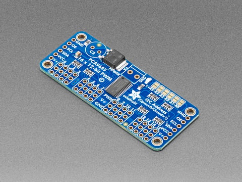
5.5.2 PCA9685 PWM Servo Driver
The Adafruit PCA9685 16-Channel 12-bit PWM/Servo Driver board generates up to sixteen independent servo PWM signals from a single I2C command stream. [12] Twelve channels drive the twelve leg servos; the remaining four channels are available for auxiliary actuators (a pan/tilt camera head, status LEDs, or a gripper payload). The board accepts 3.3 V or 5 V I2C logic from the Pi and up to 6 V on the servo power rail. Up to 62 boards can be chained to a single I2C bus by setting address pins, allowing future expansion without additional GPIO. Adafruit maintains a Python library (adafruit-circuitpython-pca9685) with ROS 2 wrapper support; TrotBot’s HAL layer demonstrates the integration directly. [5] Price is US $14.95. [12]
5.5.3 Smart Serial Alternative
Builders who choose the LX-16A upgrade path (see Actuators) require a different control path: the Pi 5’s UART (or a USB-to-TTL adapter) drives the half-duplex serial bus shared by all twelve servos in a daisy-chain topology, at 115,200 baud. [8] Hiwonder and Feetech each provide Python libraries (LX16A-bus, SCSServo SDK) that abstract the packet protocol. This path eliminates the PCA9685 from the BOM but adds a bus control adapter (approximately US $8–$20). The key advantage is joint-level position and temperature telemetry that enables the controller to detect servo overload before a thermal shutdown.
5.5.4 Power Regulation Electronics
The Pi 5 requires a stable 5 V / 3 A supply. Feeding it directly from the 11.1 V LiPo pack requires a 5 V UBEC (universal battery elimination circuit) — a small switch-mode DC-DC converter typically rated at 5 V / 3–5 A. The servo rail runs at 6–6.8 V; another UBEC or a secondary output channel steps the 11.1 V down to the servo supply voltage. Each UBEC costs approximately US $6–$12 and occupies a few cubic centimeters. An alternative commonly used in compact SpotMicro builds is a 2S 7.4 V LiPo feeding servos directly (within DS3218MG’s 4.8–6.8 V spec with some margin) and a step-up converter supplying the Pi — but voltage-spec headroom is tighter on this path. The BOM in this volume uses the 3S LiPo plus dual UBEC approach for clearer voltage headroom on both rails.
5.6 Sensors
5.6.1 Camera
The Raspberry Pi Camera Module 3 connects via CSI-2 ribbon cable to the Pi 5’s camera port. It carries a 12-megapixel Sony IMX708 sensor with autofocus and HDR support in a 25×24 mm module. [13] US price is US $29.25 as of June 2026. [13] For Build 1’s indoor teleop use case, the Module 3 is sufficient for first-person-view driving and provides a starting point for object detection experimentation via Mini Pupper 2’s YOLO11-based tracking package. [2]
The Module 3 does not provide depth data. For Build 1, depth sensing is not required — the trot gait runs in blind open-loop or IMU-assisted mode without terrain mapping. Depth sensing is a Tier-2 addition (OAK-D-Lite or OAK-D Pro, as surveyed in Volume 4).
5.6.2 IMU
The MPU-6050 is the standard IMU for Tier-1 educational builds. The Adafruit breakout board (or a generic GY-521 module) provides six axes of acceleration and angular rate over I2C for US $5–$13. [14] The MPU-6050 provides adequate orientation data to detect body roll and pitch for a simple stance-control loop and gait-state estimator. Gyroscope bias drift and noise under motor vibration are notable limitations; the CHAMP framework’s state estimator compensates with a complementary filter, and this is part of what Build 1 teaches: understanding what an IMU actually provides versus what a perfect state estimator would need.
5.7 Software
5.7.1 ROS 2 and CHAMP
Build 1’s software stack centers on ROS 2 Humble and the CHAMP quadruped controller framework. CHAMP (chvmp/champ on GitHub) is an open-source BSD-3-licensed quadruped locomotion framework implementing the MIT Cheetah I hierarchical gait controller — pattern-modulation-plus-impedance-control approach translated into a lightweight C++ library deployable on both SBCs and microcontrollers. [4] The framework accepts velocity commands from a ROS 2 navigation stack or teleop node, computes foot position trajectories using configurable stance and swing parameters, and closes the leg IK loop against the robot’s URDF description.
Although CHAMP’s main repository originally targeted ROS 1 Kinetic and Melodic, the framework’s core library has been integrated into ROS 2 by multiple community projects. The TrotBot project (2025) demonstrates the complete Pi 5 + PCA9685 + CHAMP + ROS 2 integration with full source on GitHub. [5] The Mini Pupper 2 ROS 2 stack uses a forked CHAMP controller (stan_controller) and extends it with Nav2 autonomous navigation and YOLO11 object tracking. [2] Both are MIT-licensed or BSD-licensed and available for direct adaptation.
5.7.2 Teleop and Gait
Build 1’s primary teleop interface is a Bluetooth gamepad — a Sony DualSense, Xbox controller, or Nintendo Pro Controller all work with the Pi 5’s integrated Bluetooth 5.0 and standard Linux HID drivers. The CHAMP teleop node (champ_teleop) maps gamepad axes to velocity commands; the gait controller translates those commands to leg swing trajectories at a configurable gait frequency (2–4 Hz for a stable walk, up to 6–8 Hz for a trot). [4][5]
5.7.3 Simulation Before Hardware
Before hardware calibration begins, Build 1’s URDF description should be verified in Gazebo Classic or Gazebo Sim (Ignition). TrotBot provides Gazebo integration directly; Mini Pupper 2’s ROS 2 stack includes a Gazebo simulation target. Running the controller in simulation first catches kinematic errors (wrong joint axis direction, link offset mistakes, foot contact point misplacement) before they manifest as hardware damage. Volume 4’s survey of DEEP Robotics Lite3 identified simulation-first workflows — with URDF/MJCF models validated in MuJoCo, Gazebo, and Isaac Sim — as a key differentiator in professional platform development. Build 1 is a good place to internalize that practice at small scale.
5.8 Power
Build 1’s power source is a 3S (11.1 V nominal / 12.6 V fully charged) 2200 mAh LiPo pack. The Gens Ace 2200 mAh 3S 25C pack is a representative example: US $26.79, 166 g, 106×34×22 mm, 25C continuous discharge, 50C peak. [15] Twelve DS3218MG servos draw approximately 150–300 mA each at moderate walking load; at 250 mA average per servo, total servo current is approximately 3.0 A at 6 V (18 W). The Raspberry Pi 5 at moderate CPU load draws approximately 8–12 W at 5 V. Total system draw through the 11.1 V pack is approximately 26–30 W after UBEC conversion losses, yielding an estimated runtime of (2.2 Ah × 11.1 V) / 30 W ≈ 0.81 h (~80% usable depth-of-discharge × ~85% UBEC efficiency ≈ 68% combined; 48.6 min × 0.68 ≈ 33 min, tapering to ~20 min under heavier gait load) — effectively 20–35 minutes at moderate gait speed. [15] For reference, the Mini Pupper 2 — lighter, with smaller custom servos — achieves 30–50 minutes on a 1,000 mAh pack, consistent with this estimate. [3]
Short runtime is characteristic of this tier. Battery swap takes under two minutes with a good XT60 connector mount, and a second pack costs US $27. Runtime anxiety teaches the builder to optimize gait efficiency, consider standby versus active power modes, and understand that runtime is a system-level design problem — lessons that directly inform the 10 Ah pack sizing on Tier 2.
5.9 Bill of Materials
Prices are US distributor prices as of June 2026. Items marked “est.” are community-derived estimates without a single authoritative source; hardware-store fasteners and bulk wiring consumables carry inherent price variation.
Table 2 — Bill of Materials
| Component | Qty | Unit (USD) | Total (USD) | Notes |
|---|---|---|---|---|
| Raspberry Pi 5, 8 GB | 1 | $175 [11] | $175 | ROS 2 compute, WiFi, BT |
| Adafruit PCA9685 PWM driver | 1 | $15 [12] | $15 | 16-ch I2C; drives all 12 servos |
| DS3218MG servo, 20 kg·cm, metal gear | 12 | $13 [7] | $156 | Three per leg; PWM standard |
| Raspberry Pi Camera Module 3 | 1 | $29 [13] | $29 | Sony IMX708, autofocus, HDR |
| MPU-6050 IMU breakout (GY-521 class) | 1 | $13 [14] | $13 | 6-axis I2C; adequate for Tier-1 gait |
| PLA-CF filament, 1 kg spool | 1 | $44 [10] | $44 | ~0.5–0.7 kg consumed per build |
| 3S 2200 mAh 25C LiPo (e.g., Gens Ace) | 1 | $27 [15] | $27 | 24.4 Wh; ~20–35 min runtime |
| 5 V / 3 A UBEC (Pi power supply) | 1 | $8 est. | $8 | Step-down from 11.1 V pack |
| 6 V / 3 A UBEC (servo power supply) | 1 | $8 est. | $8 | Step-down for servo rail |
| LiPo balance charger (B6 class) | 1 | $25 est. | $25 | Essential safety item |
| Wiring (XT60 connectors, JST-SH cables, servo leads) | 1 lot | $20 est. | $20 | Servo extension leads + power harness |
| M2/M3 fastener assortment | 1 lot | $10 est. | $10 | Screws, heat-set inserts, standoffs |
| Miscellaneous (heat shrink, solder, zip ties) | 1 lot | $10 est. | $10 | Consumables |
| Total | ~$540 |
LX-16A upgrade path: substitute 12× LX-16A at US $17 each [8] (US $204, +US $48 vs. DS3218MG set); the LX-16A path eliminates the PCA9685 (−$15) and adds a UART bus controller (+$15) — controller swap nets to zero — reaching approximately US $588 with superior per-joint feedback. Both configurations are viable.
5.10 Build Effort and Realistic Cost
Total parts cost falls in the US $500–$590 range depending on servo choice and whether a second LiPo pack is purchased at the outset (recommended). This places Build 1 above the SpotMicro’s community-estimated floor of US $300–$600 — that lower figure assumed MG996R servos at US $3–$5 each, which the torque check above rules out for this frame mass. [1] With properly specified servos, the realistic floor is approximately US $500.
Build time for a first-time builder should be planned as follows:
- 3D printing: 60–90 hours of machine time; split across multiple sessions. Hardware-related failures (stringing, layer adhesion, support removal damage) typically add 10–15 % to print time for a full first build.
- Mechanical assembly: 8–12 hours. Servo horn alignment, heat-set insert installation, and shoulder bracket assembly are the most time-consuming steps.
- Electronics wiring: 4–6 hours. Twelve servo connectors, dual UBEC mounting, I2C harness, and power bus require methodical cable routing and strain relief.
- Software setup: 4–8 hours to install ROS 2 Humble on the Pi 5, clone TrotBot or SpotMicroAI software, configure the URDF to match the physical build’s joint offsets, and perform servo zero-position calibration.
- Debugging and calibration: 8–20 hours (highly variable). IK calibration, PID tuning, and gait parameter adjustment are iterative processes; the first successful trot typically arrives after three to five full test sessions.
Total builder-hours: approximately 25–50 hours across two to four weekends for a methodical first build. Experienced ROS builders will compress the software phase; experienced FDM builders will compress the print and assembly phases.
5.11 Honest Limits
Build 1 is not the patrol dog. This section is explicit about what it cannot do, to calibrate expectations before the build begins.
It cannot operate outdoors reliably. PLA-CF has a glass-transition temperature of approximately 55–60 °C; a sunny day in summer will soften structural members left on concrete. [9] Rain will corrode servo PCBs and short PCA9685 traces. None of the electronics is rated for moisture ingress.
It cannot climb stairs or navigate rough terrain. Hobby servos have no compliance: an unexpected step edge loads the tibia as a lever and either strips the servo gear train or falls over. The flat, dry, indoor floor is the design envelope.
It cannot run for hours. The 20–35 minute runtime makes sustained patrol impossible. The build will spend as much time charging as walking.
Its gait will not be dynamic. CHAMP’s gait on a PWM-servo-driven build is a quasi-static walk or slow trot — no bounding, no jumping, no stair-climbing. Dynamic locomotion requires backdrivable actuators and proprioceptive torque sensing, neither of which hobby servos provide. Volume 3’s analysis of SpotMicro established this ceiling plainly: SpotMicro walks, it does not trot dynamically. [1] Build 1 extends SpotMicro’s capabilities through better servos, better compute, and better software, but it does not close the architectural gap.
It will not recognize intruders or call for help. The camera provides visual data for teleop; it is not running a trained detection model connected to an alert pipeline. Autonomous behavior at this tier means “follows a velocity command from a gamepad.” True autonomy — patrol routes, intruder alerts, GPS waypoints, night-vision thermal detection — belongs to Tier 3.
The build’s explicit purpose is to surface these limits in physical form. Every shortcoming encountered in Build 1 is a concrete data point for the Tier-2 design brief.
5.12 Lessons That Carry Up the Ladder
Build 1 generates a specific set of durable engineering knowledge that directly informs Tier 2 and Tier 3:
Servo torque is never the rated stall torque in practice. The 21.5 kg·cm stall figure on a DS3218MG is measured at locked output. Under dynamic load, with PWM duty-cycle constraints and thermal derating after fifteen minutes of walking, the effective torque is substantially lower. Tier-2 actuators (QDD BLDC) are sized based on rated continuous torque, not stall torque, specifically because Tier-1 experience shows how unreliable stall-torque margins are.
IK calibration is per-unit, not per-model. Print tolerances, servo horn alignment, and joint stop positions vary between individual builds even from identical print files. A generic URDF parameter set will not produce a level stance. Tier-2 design should include precision joint reference features (hardstops, datum surfaces) to reduce calibration effort.
ROS 2 node latency matters at gait frequencies above 4 Hz. On the Pi 5, the gait controller, servo driver, and state estimator compete for CPU time. Above 4 Hz gait frequency, jitter in the control loop becomes visible as a stumbling stride. This is a direct argument for the ESP32 sub-controller architecture (used in Mini Pupper 2) or a dedicated real-time MCU (used in all Tier-2/3 QDD platforms) on the next tier.
Wiring is a structural material. Servo lead bundles passing through leg joints that flex ±60° will fatigue and fail within hundreds of cycles. Tier-2 design must route wiring through hollow link members or provide strain-relief sleeves that cannot be imported from a flat-frame design.
Power rail sequencing matters. Powering twelve servos simultaneously before the Pi’s software is running causes voltage sag that can corrupt the boot process. A soft-start relay or MOSFET on the servo rail, controlled by a GPIO once Linux is up, is Tier-2 architecture. Build 1 teaches the need for it by failing in this mode the first time power is applied in the wrong order.
Battery sizing is system-level work. A 20-minute runtime is not a battery problem; it is a system-draw problem. Tier 2 achieves longer runtime not only by using a larger pack but by moving to 48 V QDD actuators where the same mechanical power is drawn at lower current and therefore lower I²R loss in wiring, connectors, and UBEC efficiency costs.
Each of these lessons has a direct resolution in the Tier-2 build specification: QDD actuators, precision kinematic references, a dedicated MCU, hollow link wiring, a soft-start relay, and a 48 V pack. Build 1 is the evidence base for all of them.
Sources
- SpotMicroAI documentation — readthedocs.io BOM, community build info, twelve MG996R / PCA9685 / Raspberry Pi architecture (accessed 2026-06-19) — https://spotmicroai.readthedocs.io/en/latest/gettingStarted/
- GitHub — mangdangroboticsclub/mini_pupper_ros: ROS 2 Humble stack including stan_controller, mini_pupper_navigation, mini_pupper_tracking (YOLO11), mini_pupper_driver (accessed 2026-06-19) — https://github.com/mangdangroboticsclub/mini_pupper_ros
- CNX Software — “Mini Pupper 2 — Raspberry Pi 4 / CM4 robot dog adds ESP32, ROS2 support, servo feedback”: 450 g weight, 30–50 min runtime, 1,000 mAh battery (accessed 2026-06-18) — https://www.cnx-software.com/2022/10/19/mini-pupper-2-raspberry-pi-4-cm4-robot-dog-esp32-ros2-servo-feedback/
- GitHub — chvmp/champ: Open-source quadruped locomotion framework, MIT Cheetah I hierarchical controller, BSD-3 license (accessed 2026-06-19) — https://github.com/chvmp/champ
- GitHub — mvipin/trotbot: Open-source ROS2 quadruped on CHAMP; Pi 5 + PCA9685 + 12 servos + BT gamepad; Gazebo simulation; HAL layer (accessed 2026-06-19) — https://github.com/mvipin/trotbot
- TowerPro — MG996R servo datasheet: stall torque 9.4 kg·cm @ 4.8 V, 11 kg·cm @ 6 V (accessed 2026-06-19) — https://towerpro.com.tw/product/mg996r/
- SpeedyFPV — DS3218MG product page: stall torque 19 kg·cm @ 5 V, 21.5 kg·cm @ 6.8 V; weight 60 g; price approximately US $12.99–$13 (accessed 2026-06-19) — https://speedyfpv.com/products/ds3218mg-digital-servo-high-speed-high-torque-metal-gear-waterproof-20kg-torque-180-degrees-w-accessories
- Hiwonder — LX-16A serial bus servo product page: stall torque 17 kg·cm @ 6 V, 19.5–20 kg·cm @ 7.4 V; weight 53 g; 240° rotation; UART 115,200 baud; US $16.99 (accessed 2026-06-19) — https://www.hiwonder.com/products/lx-16a
- North Lakes Design — “PLA-CF vs PETG-CF: Selecting 3D Printing Materials for Maximum Durability” (stiffness, Tg 55–60 °C, brittleness vs. impact absorption comparison) (accessed 2026-06-19) — https://www.northlakesdesign.co.uk/blog/selecting-3d-printing-materials-for-maximum-durability-pla-cf-vs-petg-cf
- Newegg — TINMORRY PLA-CF Carbon Fiber PLA Filament 1.75 mm, 1 kg, Black: US $43.54 (accessed 2026-06-19) — https://www.newegg.com/p/298-00MW-001Y4
- PiShop.us — Raspberry Pi 5 8 GB: US $175.00 (accessed 2026-06-19) — https://www.pishop.us/product/raspberry-pi-5-8gb/
- Adafruit — PCA9685 16-Channel 12-bit PWM/Servo Driver: US $14.95 single unit (accessed 2026-06-19) — https://www.adafruit.com/product/815
- PiShop.us — Raspberry Pi Camera Module 3: US $29.25; Sony IMX708 12 MP, autofocus, HDR (accessed 2026-06-19) — https://www.pishop.us/product/raspberry-pi-camera-module-3/
- Adafruit — MPU-6050 6-DoF Accel and Gyro Sensor STEMMA QT Qwiic: US $12.95 single unit; 6-axis I2C; 26×17.8×4.6 mm; 1.8 g (accessed 2026-06-19) — https://www.adafruit.com/product/3886
- Gens Ace / GenStattu — Gens Ace 2200 mAh 3S 25C 11.1 V G-Tech LiPo: US $26.79, 166 g, 106×34×22 mm, 25C continuous / 50C peak (accessed 2026-06-19) — https://genstattu.com/gens-ace-2200mah-3s-25c-11-1v-g-tech-lipo-battery-pack-with-deans-plug/