Conte Lethal Injection Attack Droid · Volume 6
Construction II — Control Electronics & Programmability
Sourcing note. The museum called this a “programmable robotic sculpture,” and the deck carries a genuine Parallax circuit board (its silkscreen reads “PARALLAX Inc”). Beyond the brand, no schematic, parts list, firmware, or wiring diagram for the piece is published. This volume separates three things and labels each: (a) what the photographs of this board show; (b) documented, general facts about the Parallax BASIC Stamp family that was Parallax’s programmable platform in 2004; and (c) inference connecting the two. It does not claim a specific SKU, a motor type, or a control program as fact.
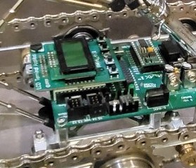
6.1 What the photographs show on the deck
A green printed-circuit board is mounted flat and longitudinally on the centre of the chassis, spanning the gap between the two tracks. Reading the board from this hub’s close-up photographs:
- The silkscreen carries the “PARALLAX Inc” maker’s mark — this is a genuine Parallax product, not a generic perfboard.
- A socketed module sits at one end in an inline (SIP-style) socket — the form factor of a plug-in Parallax BASIC Stamp module, the company’s programmable brain of the era.
- An onboard voltage-regulator section: a TO-220-style regulator flanked by two electrolytic capacitors — the standard “raw battery in, regulated 5 V out” front end of a Parallax carrier board.
- A labelled “9 Vdc Battery” power input — consistent with the 9-volt battery supply Parallax carrier boards are designed around.
- Rows of male header pins along the board (the broken-out I/O field) and what reads as a reset/control area.
- A second, smaller green daughterboard stacked beneath/beside the main board, carrying additional ICs. Given a robot with two tracks to drive, the most plausible role for this added board is motor / servo drive — the interface between the controller’s logic-level I/O and whatever actuators move the tracks and arm. (Role inferred, not documented.)

6.2 Context: what “a Parallax board, 2004” means
To read the deck responsibly, it helps to know what Parallax actually sold in 2004. The following is documented general background about Parallax products, not a claim about this specific board:
- Parallax’s flagship programmable controller in 2004 was the BASIC Stamp — a small module with a microcontroller running a tokenised-BASIC interpreter, sold as a socketed brain that plugs into a carrier board. The BASIC Stamp 2 (BS2) was the mainstream member.
- A BASIC Stamp 2 module integrates, on one small PCB: the interpreter chip (a Microchip PIC rebranded by Parallax), a serial EEPROM that holds the user’s program, a clock resonator, a 5 V regulator, and reset circuitry. It exposes 16 general-purpose I/O pins.
- It is programmed in PBASIC, Parallax’s dialect, downloaded over a serial (later USB) link from a PC. Programs are stored in the EEPROM and re-run on power-up, so the device is self-contained once programmed.
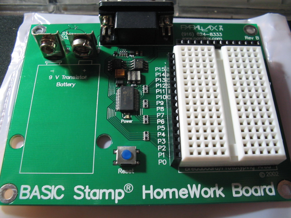
- Typical carrier boards of the era — the Board of Education, the BASIC Stamp Carrier Board, the HomeWork Board, and the Boe-Bot robot controller — provide the BS2 socket, a 9 V battery input, the 5 V regulator, the programming connector, and broken-out I/O headers, often with servo headers for hobby robotics. Parallax’s Boe-Bot (a BS2-driven two-servo robot) made this the default “first robot” platform of the period.
- The BASIC Stamp can drive R/C-style hobby servos directly with a single
PULSOUT/timing loop, and can drive DC motors through an external motor driver (e.g. an H-bridge) — which is exactly the function a stacked daughterboard would add.

6.3 Inference: reading this board
Putting the two together, with appropriate hedging:
Table 1 — Putting the two together, with appropriate hedging
| Question | Best reading from the evidence | Confidence |
|---|---|---|
| Is it really Parallax? | Yes — silkscreen “PARALLAX Inc” | Documented (visible) |
| What class of controller? | A BASIC Stamp-family module on a Parallax carrier board | High (form factor + brand + era) |
| Exact SKU (BS2 vs BS2sx/p; which carrier) | Not determinable from the photographs; consistent with a BS2-class module on a carrier such as a Board of Education / Carrier Board | Inference only |
| What is the second board? | Most plausibly a motor/servo driver added to drive the tracks/arm | Inference only |
| Language / programming | PBASIC over serial, program stored in onboard EEPROM (how every BASIC Stamp works) | Documented for the family |
| Power | A 9 V battery feeding an onboard 5 V regulator (label + visible regulator) | High (visible) |
| Did it ever actually run/drive? | Not documented. The live controller makes powered function plausible but unproven | Unknown |
This deep dive deliberately stops at “a BASIC Stamp-class Parallax board.” The exact model is not legible or published, and inventing one would violate the hub’s no-fabrication rule. What matters and is certain: the sculpture carries a real, period-correct, programmable microcontroller, not a dummy prop.
6.4 Why the controller is the conceptual core
As argued in Vol 2, the choice to make the piece genuinely programmable is the hinge of its meaning. A BASIC Stamp is a small, self-contained agent that, once programmed and powered, executes its stored PBASIC program autonomously — it can sense, wait, decide on a condition, and actuate without a human in the loop. That faculty is precisely the “human involvement” the placard says the work imagines eliminating from an execution. The 9 V battery, the EEPROM-stored program, and the motor-driver daughterboard together describe an object that could, in principle, run a sequence on its own — drive forward, position the arm, actuate the syringe — which is the unsettling capability the sculpture is built to contemplate. The hardware is modest and hobby-grade; the idea it embodies is not.
The next volume turns to what that controller would ultimately be commanding: the manipulator arm and the vintage glass syringe at its tip.
Comments (0)