Heathkit HERO 1 (ET-18) · Volume 2
Hardware Architecture — A 6808 on a Single Bus
2.1 The processor at the center
Every action a HERO 1 takes — a wheel turning, the head swinging to aim, a
phoneme leaving the speech board — is ultimately a byte written or read by one
8-bit microprocessor. That processor is a Motorola 6808 running at 1 MHz
(Wikipedia, “HERO (robot)”; hero.dsavage.net HERO FAQ; makezine.com). The
6808 is a member of the 6800 family: the same instruction set and the same
register model as the original 6800, but built without the on-chip clock
oscillator of the 6802 and without on-chip RAM, so it depends entirely on
external memory and an external clock. For a robot that is, at bottom, a
teaching platform, that simplicity is the point — the bus is exposed, the parts
are countable, and the machine can be reasoned about end to end.
A 1 MHz 6800-class part executes most instructions in a handful of machine cycles, which places the HERO 1 firmly in the era’s slow, deterministic control-loop regime: there is no operating system underneath the program, no memory protection, and no pipeline to reason around. The robot monitor in ROM and whatever program the operator has entered share one flat 64 KB address space, and the processor walks through it one instruction at a time. This makes the HERO 1 an honest object of study — the kind of machine an engineer can hold entirely in their head.
2.1.1 Why a single bus matters
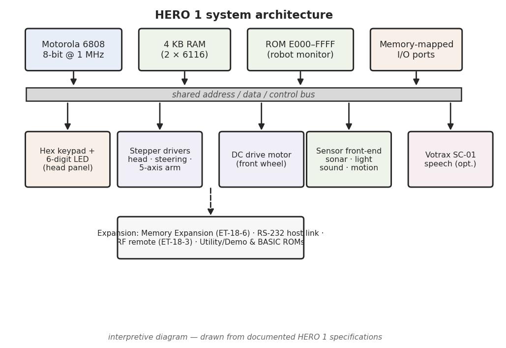
The architecture sketched in Figure 1 is the defining fact of the machine: a
single shared bus to which memory and every peripheral are attached, with
the peripherals appearing to the processor not as I/O ports behind special
instructions but as ordinary memory addresses. The 6800 family has no separate
I/O address space and no IN/OUT instructions — a design choice it inherited
and the HERO 1 lived by. To turn a motor or read a sensor, the program does
exactly what it does to touch RAM: it writes to, or reads from, an address. That
is memory-mapped I/O, and it is the bridge between the processor and the
rest of this deep dive — the drive and steering of Vol. 3, the head and arm of
Vol. 4, the sonar/light/sound/motion sensing of Vol. 5, and the Votrax speech of
Vol. 6 all hang off the bus as addressable devices.
The consequence for the programmer is direct: there is no API between the code and the hardware, only addresses. A motion command is a store; a sensor reading is a load. Vol. 7 takes up how the operator actually issues those stores and loads — by hand from the hex keypad, from the teaching pendant, or from a host over RS-232 — but the mechanism underneath all of those routes is the same bus traffic shown here.
2.2 Memory
2.2.1 RAM — 4 KB as two 6116s
The HERO 1 carries 4 KB of static RAM, implemented as two 6116 chips of 2 KB each (HERO FAQ). The 6116 is a standard 2K×8 static RAM of the period — no refresh logic, no DRAM controller, just a chip that holds its contents as long as it has power. Two of them side by side give the flat 4 KB working store in which the operator’s program, its variables, and the monitor’s own scratch landmarks all live.
Four kilobytes is a small canvas, and it sets the scale of what an unexpanded HERO 1 could be asked to do: programs were short, hand-entered sequences of 6808 machine code, not large compiled images. When more room was needed — notably to run HERO-1 BASIC — it came from the optional Memory Expansion board (ET-18-6) rather than from the base machine; that board, and the host link that often accompanied it, are covered in Vol. 7.
2.2.2 ROM — the robot monitor
The firmware that brings the HERO 1 to life is its robot monitor — the resident program that scans the keypad, drives the LED display, and provides the primitives for entering, examining, and running code, as well as the routines that command motion. The deep dive describes this firmware as “the robot monitor” throughout, and that is deliberate, because the two best secondary sources describe its size differently and the difference is worth stating plainly.
- Wikipedia describes the firmware as a 2 KB monitor ROM.
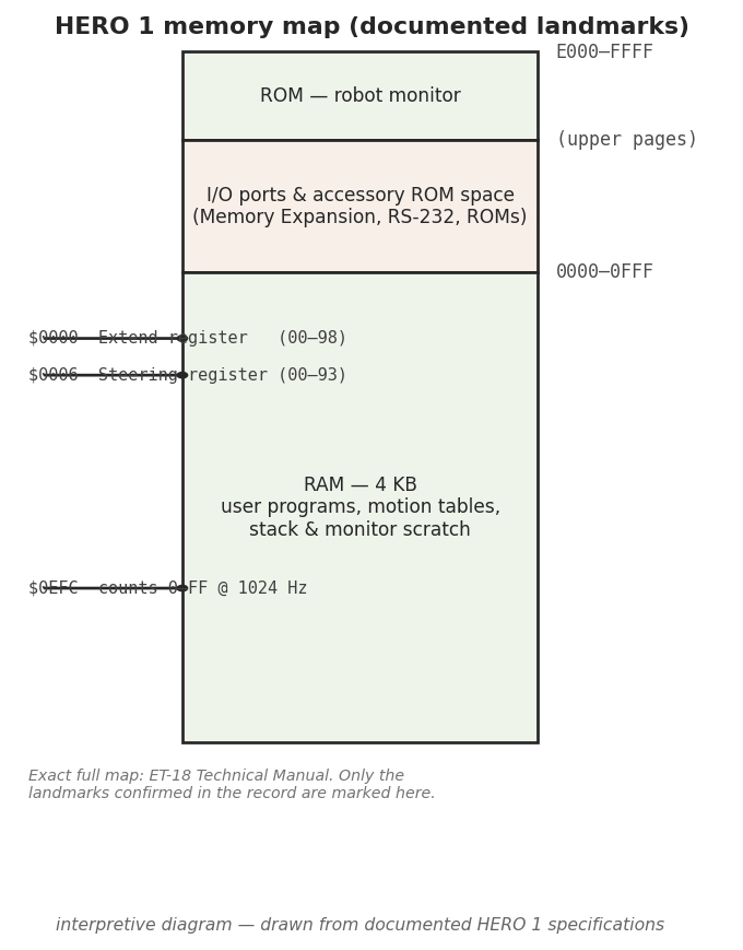
- The HERO FAQ’s memory map shows ROM occupying the E000–FFFF range — an address window of up to 8 KB.
These two statements are not necessarily in conflict. A monitor of roughly 2 KB can sit inside a larger ROM address space, and a part decoded across E000–FFFF need not have every byte of that window populated. The honest reading, and the one this series holds to, is that the HERO 1 runs a robot monitor on the order of 2 KB, residing within a ROM address region reported as E000–FFFF — without asserting a single ROM chip size as settled fact (Wikipedia; HERO FAQ). The 6808 takes its reset and interrupt vectors from the top of memory, so a ROM placed at the high end of the address space, ending at FFFF, is exactly where a 6800-family monitor belongs.
2.2.3 Documented monitor landmarks
A handful of specific RAM locations are documented in the HERO FAQ as the monitor’s working registers — the addresses a program reads or writes to learn what the robot is doing and to tell it what to do next. These are the few firm points on an otherwise unreconstructed map, and they are reproduced here exactly as the source gives them.
Table 1 — Documented monitor landmarks
| Address | Role | Source |
|---|---|---|
| $0000 | ”Extend” register, value range 00–98 | HERO FAQ |
| $0006 | ”Steering” register, value range 00–93 | HERO FAQ |
| $0EFC | Counter, 00–FF, incremented at 1024 Hz | HERO FAQ |
Three observations follow, each gated to what the source actually states. First, all three landmarks sit low in memory, inside the 4 KB RAM region — $0000 and $0006 in the very first bytes of the address space, and $0EFC near the top of the second 6116. This is consistent with a 6800-family monitor that keeps its live state in low RAM, where the family’s direct (zero-page) addressing mode can reach the first 256 bytes most compactly.
Second, the $0EFC counter advancing at 1024 Hz is a timebase landmark: a location the firmware ticks 1024 times a second, wrapping through its 00–FF range about four times per second. It is the kind of free-running counter a program reads to measure intervals or to pace a motion without a dedicated hardware timer in front of it (HERO FAQ).
Third — and this is the cross-reference to keep in view — the $0000 “Extend” and $0006 “Steering” registers are not abstract status bytes; they are how a program commands the robot’s motion. Their value ranges (00–98 and 00–93) read like commanded set-points rather than free counters, which is precisely how Vol. 7 uses them: as the concrete, documented example of issuing a motion command by writing a memory-mapped register. The mechanical meaning of “steering” — the front wheel that both drives and steers — belongs to Vol. 3; here the point is only that the steering command is a byte at a known address.
2.2.4 What is deliberately left unclaimed
The three rows above are the documented landmarks, and nothing beyond them is reconstructed here. The HERO 1’s complete memory map — every peripheral address, every monitor entry point, the exact decode of the I/O region, and the precise placement and size of the ROM — lives in the ET-18 Technical Manual, part of the factory manual set, which a restorer or programmer should consult as the authoritative primary source. This volume does not invent addresses to fill the gaps between the known points. Where the secondary record is silent, the map is left blank rather than guessed (protocol §7; no-fabrication rule).
2.3 Peripherals on the bus
Because the HERO 1 uses memory-mapped I/O, the long list of things the robot can do reduces, at the bus level, to a list of addresses. The processor reaches each subsystem the same way — a load or a store — and the subsystem’s electronics do the rest. The subsystems themselves are the subject of later volumes; what matters architecturally is only that each one is a device on the single bus of Figure 1:
- Drive and steering — the front wheel’s DC drive and steering motors, commanded through monitor registers such as the $0006 Steering byte (Vol. 3).
- Head — the 350°-rotating head that aims the sensor cluster and the arm (Vol. 4).
- Arm — the optional five-axis manipulator (ET-18-1), stepper-driven with potentiometer position feedback (Vol. 4).
- Sensing — sonar ranging, the light detector, the sound detector, and the motion detector, each returning data the processor reads back over the bus (Vol. 5).
- Speech — the optional Votrax SC-01 phoneme synthesizer board (ET-18-2), fed a stream of phoneme codes by the program (Vol. 6).
- Console — the 17-key hexadecimal keypad and the six-digit seven-segment LED display on the head, the monitor’s own human interface (Vol. 7).
None of these needs a special instruction or an I/O port; each is simply memory, and that uniformity is what makes a 1 MHz 8-bit processor sufficient to run a robot of this complexity.
2.4 Power
The architecture above runs on a self-contained DC supply. The HERO 1 carries four gel-cell rechargeable batteries as its onboard power source, and ships with a 120/240 VAC, 50/60 Hz charger to replenish them (HERO FAQ; theoldrobots.com). The dual-voltage, dual-frequency charger is consistent with a product Heathkit sold internationally. Gel cells — sealed lead-acid batteries with the electrolyte immobilized as a gel — were the sensible choice for a mobile robot of the era: rechargeable, orientation-tolerant, and capable of the surge current a DC drive motor and seven stepper motors demand, without the spill risk of a flooded cell.
A note on attribution is warranted. theoldrobots.com documents “four gel cell”
batteries, and the 6 V per-cell value is widely reported for the HERO 1; the
firm, multiply-sourced claim is simply four gel-cell rechargeable batteries
with an included 120/240 VAC charger (HERO FAQ; theoldrobots.com). The
practical consequences of that battery chemistry for a machine being restored
today — aged packs, charging cautions, and the mains-charger safety posture —
are taken up in Vol. 8 and in _shared/safety.md.
2.5 Reading the architecture as a whole
Put together, the HERO 1’s hardware is a single 8-bit story. A 6808 at 1 MHz sits on one bus. Below it on that bus is 4 KB of static RAM in two 6116s, holding the operator’s program and the monitor’s live state — including the documented $0000, $0006, and $0EFC landmarks. High on the bus is the robot monitor in ROM, reported around 2 KB and addressed in the E000–FFFF region. Between them is a band of memory-mapped I/O through which drive, steering, head, arm, sensors, speech, and the keypad/LED console are all reached as ordinary addresses. And underneath everything is a four-cell gel-cell pack charged from the wall.
That is the whole machine at the bus level. The volumes that follow open each device on that bus in turn — but every one of them, when a program runs, comes back to the same act: the 6808 placing an address on the bus and moving a byte. The exhaustive map of which byte goes where is the ET-18 Technical Manual’s to give; this volume has set the frame into which those addresses fit.
Comments (0)