Heathkit HERO 1 (ET-18) · Volume 7
Programming & Control — Keypad, Pendant, Remote, and Host
7.1 How a program reaches the 6808
Everything the HERO 1 does begins as bytes in the memory of its single Motorola 6808, the 1 MHz 8-bit processor examined in Vol. 2. The robot has no disk, no tape, and — in its base configuration — no keyboard in the ordinary sense. The question this volume answers is the practical one: by what routes does an operator get instructions into that 6808, and once they are there, in what language are they written?
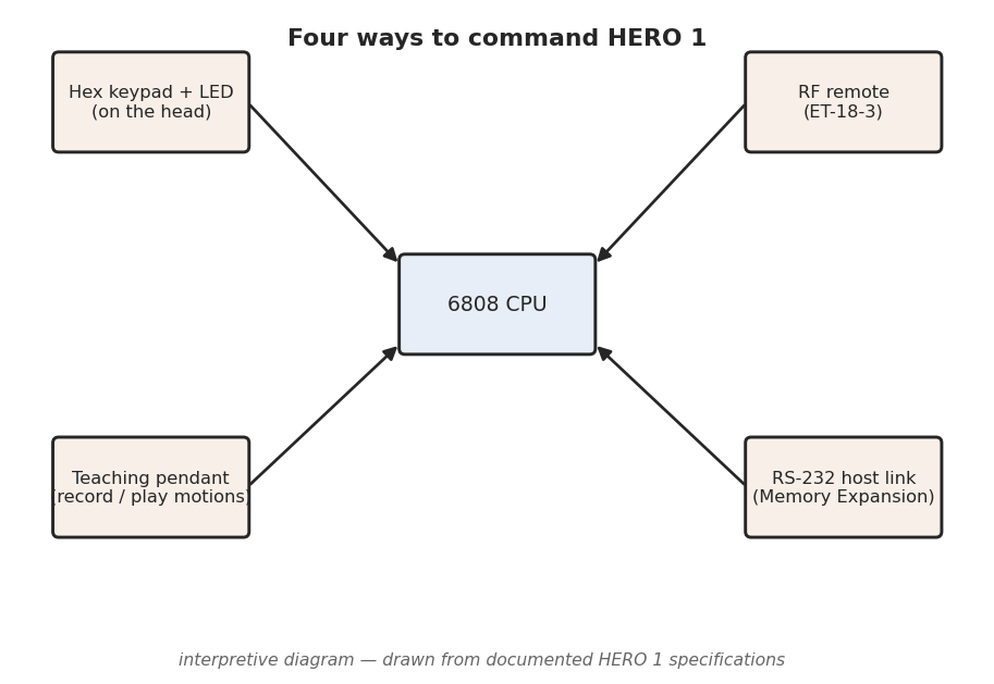
There are four documented control routes into the processor, and they form a deliberate ladder from the most primitive to the most capable. At the bottom is the 17-key hexadecimal keypad and the six-digit LED built into the head, the only input the base robot ever needs. Above it sits the teaching pendant, a hand controller that lets the operator drive the robot by hand and record what it did. Two optional links extend the reach further: an RF remote transmitter (documented in the Remote Operation manual, ET-18-3) for untethered manual control, and an RS-232 host link carried on the optional Memory Expansion board (ET-18-6) that connects the robot to a full-sized computer (HERO FAQ; Wikipedia, “HERO (robot)”; theoldrobots.com).
Layered on top of those physical routes are the programming languages. By default the operator writes 6808 machine code by hand and keys it in as hex. With the Memory Expansion board fitted, the HERO-1 BASIC ROM (ET-18-9) turns the same robot into a BASIC-programmable machine. Two further accessory ROMs — the Utility/Demo ROM (ET-18-4) and the Automatic Mode ROM (ET-18-7) — add canned behaviour and self-directed operation without the operator writing a line of code (HERO FAQ; ET-18 manual set).
7.2 The four control routes
7.2.1 Route 1 — the hex keypad and six-digit LED
The primary interface is built into the top of the head: a 17-key hexadecimal keypad paired with a six-digit, seven-segment LED display (Wikipedia; HERO FAQ; theoldrobots.com). Sixteen of the keys are the hex digits 0–F; the seventeenth is a function/command key used to select what the keypad and display are doing — examining memory, depositing a byte, selecting a mode, or running a program. The exact key legends and the full command syntax are laid out in the ET-18 Technical Manual; this volume gates only to the documented fact that the panel is 17 keys plus a six-digit display.
This is a monitor-style interface, the same idiom the KIM-1 and a generation of single-board computers used: the LED shows an address and the byte stored there, and the keypad lets the operator step through memory, change bytes, and launch execution. Because the display has six digits, it can show an address and its data side by side — a four-hex-digit address (the 6808 addresses a 64 KB space) leaves room for a two-digit data byte, which is exactly what memory-examination needs. The operator enters a program as a sequence of machine -code bytes, verifies each by reading it back on the LED, and modifies any byte in place before running — the three operations Heathkit’s documentation attributes to the panel: enter, verify, modify (Wikipedia; HERO FAQ).
The keypad is also how the operator selects the robot’s mode. The robot monitor in ROM presents a small menu of operating modes — keyboard/program mode, the various accessory-ROM modes when those ROMs are fitted, and so on — and the function key plus a digit chooses among them. With no accessories at all, the keypad and LED are a complete development environment: a person can write, key in, debug, and run a 6808 program without attaching anything else to the robot.
7.2.2 Route 2 — the teaching pendant
The teaching pendant is a hand-held controller, tethered to the robot, that lets an operator drive the HERO 1 manually and record the motions for later replay (HERO FAQ). It is the robot-arm world’s classic “teach-and-repeat” paradigm brought down to a hobby machine: rather than computing joint values and keying them in as hex, the operator moves the robot by hand through a sequence — roll forward, rotate the head, swing the shoulder, close the gripper — and the monitor captures the commanded values as it goes. Playing the recording back re-issues the same commands in the same order, and the robot repeats the taught motion.
Mechanically this works because every HERO 1 motion is ultimately a value written to a memory-mapped register (the worked example below shows two of them). When the pendant drives an axis, the monitor is writing those same registers; the “recording” is the captured stream of register writes, and “play” replays it. The precise capacity of a taught sequence, and the exact pendant button layout, are documented in the ET-18 manual set rather than the secondary record, and are left unclaimed here — the firm, documented fact is the record/play teaching model itself (HERO FAQ). The teaching pendant is the bridge between the two extremes of the control ladder: more capable than hand-keying hex, but requiring no programming language at all.
7.2.3 Route 3 — the RF remote transmitter (ET-18-3)
The optional RF remote is an untethered transmitter that controls the robot over a radio link, documented in the Remote Operation manual, ET-18-3 (HERO FAQ). It was offered in two frequency models, so that two robots — or a robot and a nearby second transmitter — could operate without interfering with each other (HERO FAQ). The exact assigned frequencies are not part of this deep dive’s gated fact base and are left to the ET-18-3 manual; the documented claim is simply a two-model RF remote.
Functionally the remote is a wireless extension of manual control: it lets an operator drive the robot and command its motions from across a room without the pendant’s tether, which matters for demonstrations and for the entertainment use Heathkit marketed (Vol. 1). It does not change what the 6808 can be told to do — it is another way of issuing the same motion commands — but it removes the cable, which for a mobile robot is a meaningful gain.
7.2.4 Route 4 — the RS-232 host link (ET-18-6)
The fourth route turns the HERO 1 from a stand-alone machine into the peripheral of a larger computer. The optional Memory Expansion board, ET-18-6, carries an RS-232 serial interface; with it fitted, a host computer can be wired to the robot and can exchange data with the 6808 over the serial line (HERO FAQ; theoldrobots.com). The RS-232 interface is an optional addition rather than a port present on the base machine — it arrives with the ET-18-6 expansion (the robot’s user-accessible experimental breadboard, covered in Vol. 5, is the documented area for an experimenter’s own additions) (theoldrobots.com).
The host link serves two purposes. First, it lets a programmer develop on a comfortable full-sized computer — with a real keyboard, screen, and editor — and download the assembled program to the robot, instead of hand-keying hundreds of hex bytes through the head panel. Second, the memory expansion the same board provides is what makes the larger programming languages practical: HERO-1 BASIC (below) requires the expansion to have room to run. The RS-232 link is thus both a development convenience and the physical prerequisite for the robot’s most capable software.
7.3 The programming layers
The four routes above are how instructions get in; the layers below are what the instructions are written in. They stack from the bare machine upward.
7.3.1 Default — 6808 machine code from the keypad
Out of the box, the HERO 1 is programmed in Motorola 6808 machine code, keyed in as hexadecimal through the head panel (HERO FAQ; Wikipedia). There is no assembler in the base robot and no higher language: the operator works out the program by hand — or assembles it on paper or another machine — reduces it to a sequence of opcode and operand bytes, and deposits those bytes into RAM one at a time using the keypad’s examine/deposit commands. The six-digit LED shows each address and the byte being stored, so the operator can verify the entry as it goes.
Because the 6808 is a member of the Motorola 6800 family, its instruction set, addressing modes, and opcode encodings are exactly those of the well-documented 6800/6808 — the ET-18 Technical Manual and any 6800-family programming reference describe them. What the HERO 1 adds on top is the robot monitor in ROM and the memory-mapped registers it exposes: the program achieves motion and reads sensors not through special instructions but by ordinary 6808 loads and stores to specific addresses (Vol. 2). Writing a value to the steering register turns the wheel; reading the sonar register returns a range. Machine-code programming on the HERO 1 is, in practice, the discipline of knowing which addresses do what — which is why the documented register landmarks below matter so much.
7.3.2 HERO-1 BASIC — the ET-18-9 ROM
For operators who did not want to hand-assemble 6808 code, Heathkit offered HERO-1 BASIC, supplied as the ET-18-9 ROM and documented in its own HERO-1 BASIC manual (HERO FAQ; ET-18 manual set). BASIC raises the programming layer from raw opcodes to a structured, English-like language with variables, loops, and named commands for the robot’s motions and sensors — a far more approachable way to write behaviour than depositing hex.
The crucial constraint is that HERO-1 BASIC requires the Memory Expansion board (ET-18-6) to run; the base robot’s 4 KB of RAM (Vol. 2) is not enough to hold a BASIC interpreter’s working space alongside a user program (HERO FAQ). The two optional boards therefore travel together: the expansion provides both the RAM headroom BASIC needs and the RS-232 link over which a BASIC program can be developed on a host and sent down. With the ET-18-9 ROM and the expansion fitted, the same physical robot that otherwise demands hand-keyed machine code becomes a BASIC-programmable platform — a substantial jump in accessibility, and the configuration most often used for teaching once a school had budget for the options.
7.3.3 The Utility/Demo ROM (ET-18-4) and the Automatic Mode ROM (ET-18-7)
Two further accessory ROMs let the robot do useful things without the operator writing any program at all. The Utility/Demo ROM, ET-18-4, supplies built-in demonstration and utility routines — canned behaviours that exercise the drive, the head, the arm, and the sensors so a new owner can confirm the machine works and show it off before learning to program it (HERO FAQ; ET-18 manual set). The Automatic Mode ROM, ET-18-7, adds self-directed operation: with it fitted and selected from the keypad, the robot runs an autonomous behaviour — sensing its surroundings and acting on them — rather than waiting for keyed-in or remote-issued commands (HERO FAQ; ET-18 manual set).
Both are selected through the head keypad’s mode menu (Route 1), and both illustrate the HERO 1’s layered design: the robot monitor in the base ROM defines the modes and the register interface, and an accessory ROM slots into that framework to add a behaviour. The exact contents of each ROM — which demos, which automatic behaviours — are enumerated in their respective ET-18 manuals and are left there; the documented facts gated here are the part numbers and the roles: ET-18-4 is the Utility/Demo ROM, ET-18-7 the Automatic Mode ROM.
7.4 A worked example — commanding motion through the monitor registers
The clearest way to see how all four routes ultimately do the same thing is to trace a single motion down to the bytes. Every documented control route ends in the same place: a value written to a memory-mapped register that the robot monitor reads and acts on. Two such registers are documented in the secondary record and serve as a concrete example (HERO FAQ):
Table 1 — record and serve as a concrete example (HERO FAQ)
| Address | Register | Documented value range | What it commands |
|---|---|---|---|
$0000 | Extend | 00–98 | How far an axis is extended |
$0006 | Steering | 00–93 | The front-wheel steering angle |
Consider steering. The HERO 1 rolls on three wheels — two fixed at the rear, one
steerable drive wheel at the front (Vol. 3) — and the angle of that front wheel
is governed by the value stored at $0006, which the HERO FAQ documents as
ranging from 00 to 93 (hex). In 6808 machine code, commanding a steering
angle is therefore as simple as loading a value into the accumulator and storing
it at that address — conceptually:
LDAA  #$4A      ; a mid-range steering value (example)
STAA  $0006     ; write it to the Steering register
The monitor, running its 1024 Hz timing loop (the $0EFC counter documented in
Vol. 2), picks up the new value and drives the steering motor (Vol. 3) until the
wheel reaches the commanded angle. The Extend register at $0000,
documented over the range 00–98, works the same way for an extension axis:
store a value, and the corresponding mechanism extends to match.
This single mechanism explains every route in this volume:
- Keypad (Route 1): the operator keys the bytes
B7 00 06(store-to-$0006) and a value directly into RAM and runs them — hand-written machine code doing the store. - Teaching pendant (Route 2): moving the steering by hand makes the monitor
write
$0006for the operator; “record” captures the value, “play” re-writes it. - RF remote (Route 3): a steering command on the transmitter is decoded by the robot and lands as the same register write.
- Host link (Route 4) / BASIC: a BASIC
STEER-style command, or a byte sent over RS-232, ultimately resolves to the monitor storing a value at$0006.
The registers above are the only memory landmarks this deep dive asserts as
addresses; $0000 Extend, $0006 Steering, and the $0EFC 1024 Hz counter come
from the HERO FAQ, and every other address — the sensor registers, the head and
arm controls, the full I/O map — lives in the ET-18 Technical Manual, which a
programmer must consult to write real HERO 1 code. The point of the example is not
the specific addresses but the pattern: HERO 1 programming is memory-mapped
motion, and all four control routes are different front ends to the same byte
written to the same register.
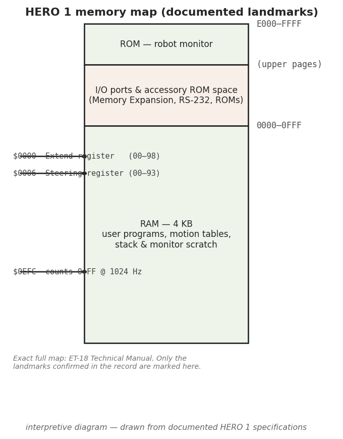
$0000 Extend and $0006 Steering registers a stored value commands, and the
$0EFC 1024 Hz timing counter the monitor runs on. The exhaustive map lives in the
ET-18 Technical Manual. Interpretive diagram drawn from documented HERO 1
specifications.7.5 Accessories and ROMs at a glance
The control routes and programming layers above are spread across the base robot and a set of optional boards and ROMs, each with its own ET-18 part number and its own manual in the freely available ET-18 manual set. The table below collects the accessories relevant to programming and control alongside the rest of the documented ET-18 line, so the part numbers cited throughout this series sit in one place (HERO FAQ; ET-18 manual set):
Table 2 — place (HERO FAQ; ET-18 manual set)
| Accessory / ROM | Part # | Role |
|---|---|---|
| Manipulator arm | ET-18-1 | Optional five-axis arm + gripper (Vol. 4) |
| Speech synthesizer | ET-18-2 | Votrax SC-01 phoneme speech board (Vol. 6) |
| Remote operation | ET-18-3 | RF remote transmitter, two frequency models (Route 3) |
| Utility/Demo ROM | ET-18-4 | Built-in demonstration and utility routines |
| Memory Expansion board | ET-18-6 | Added RAM + RS-232 host interface (Route 4) |
| Automatic Mode ROM | ET-18-7 | Self-directed autonomous operation |
| HERO-1 BASIC ROM | ET-18-9 | BASIC language — requires the ET-18-6 expansion |
The numbering is not fully contiguous in the secondary record: the entries above are the documented ET-18 accessories, and any gap in the sequence is left unclaimed rather than filled in. The base robot — keypad, LED, teaching pendant, robot monitor in ROM, and 4 KB of RAM — carries no separate accessory number; it is the ET-18 (assembled) / ETW-18 (kit) machine itself (Vol. 1).
7.6 Where this fits in the series
This volume covered how instructions reach the 6808 and what they are written in; the rest of the series covers what those instructions then drive. The hardware that decodes and executes them — the 6808, the RAM, the ROM monitor, and the memory-mapped I/O that the register example depends on — is the subject of Vol. 2. The steering and Extend registers used in the worked example command the drive and the actuators detailed in Vol. 3 (the three-wheel base and its motors) and Vol. 4 (the head and the five-axis arm). The sensor registers a program reads back — sonar, light, sound, and motion — are described in Vol. 5, and the speech a program can command through the ET-18-2 board is in Vol. 6. Vol. 8 returns to the control hardware from the restorer’s side, and Vol. 9 gathers every part number and documented landmark, including the ET-18 accessory list above, into the cheatsheet.
Comments (0)