Heathkit HERO 1 (ET-18) · Volume 4
The Head & the 5-Axis Arm
4.1 The head as a platform
Most of what makes the HERO 1 feel like a robot lives on its head. The hex keypad and the six-digit LED display sit there; so does the sonar transducer and the cluster of light, sound, and motion sensors covered in Vol. 5; and so does the mounting point for the optional manipulator arm. The head is not just a styling element wrapped around the electronics — it is the robot’s orientable instrument platform, and the single design decision that defines it is that the whole head rotates with respect to the base.
That rotation is documented as 350° (HERO FAQ; Wikipedia; theoldrobots.com). Not a full 360° — the head sweeps through 350° and stops, which is the signature of a single rotary joint with a hard travel limit rather than a continuous slip-ring drive. A continuous-rotation joint would need brushes or a slip ring to carry power and signal across an unbounded turn; a joint that stops just short of a full turn can run its wiring as a simple cable harness that twists and untwists within the 350° arc. The 10° the head gives up buys a much simpler, more reliable electrical path to everything mounted on the head.
4.1.1 Why a rotating head matters
The value of the rotating head is that it lets the robot aim without driving. The HERO 1’s locomotion is a three-wheel base with a single steerable front drive wheel (Vol. 3): turning the body to face a new direction means executing a steering-and-drive maneuver, consuming battery, and changing the robot’s position on the floor. The head sidesteps all of that. A stationary HERO 1 can point its sonar, its sensor cluster, and — if fitted — its arm through nearly a full circle by rotating only the head, leaving the base planted (HERO FAQ; Wikipedia).
For a sensing-and-manipulation robot this separation of aiming from moving is the whole point. Scanning a room for the nearest obstacle becomes a head sweep, not a pirouette. Bringing the arm to bear on an object to one side becomes a head rotation plus an arm reach, with the heavy, friction-bound drive train left idle. The head is, in effect, the robot’s pan axis, and the sensors and the arm are the payload it carries around that axis.
The drive for the head rotation is one of the seven stepper motors the HERO FAQ attributes to the machine (“seven stepper motors control all movements”). As Vol. 3 discusses, the exact allocation of those seven steppers across steering, head rotation, and the arm is not cleanly itemized in the secondary record and is treated here as interpretive; what is firm is that the head’s rotation is a stepper-driven motion, distinct from the DC motors that drive and steer the front wheel (HERO FAQ).
4.2 The optional arm — ET-18-1
The manipulator arm is not part of the base machine. It is the optional ET-18-1 accessory (the arm carries its own ROM/part number in the ET-18 family, alongside ET-18-2 speech, ET-18-3 remote operation, and the rest — see the accessory list in Vol. 7). A HERO 1 could be bought, built, and programmed with no arm at all; the arm bolts on as an upgrade and is what turns the robot from a sensing platform into something that can reach into its environment and move a small object.
The firm, documented facts about the arm are deliberately few, and this volume holds to them:
- Five axes plus a gripper. (HERO FAQ)
- Maximum lift of approximately 16 oz — about one pound. (HERO FAQ)
- Stepper-motor-driven joints with potentiometer position feedback. (HERO FAQ)
Everything beyond those three statements — in particular, any specific naming or ordering of the five axes — is an interpretive reading, and is flagged as such below.
4.2.1 Five axes plus a gripper
“Five axes” is the load-bearing number, and it is worth being precise about what it does and does not say. An axis is one independently driven degree of freedom — one joint the program can command to a position. Five axes means the arm can be commanded into five independent joint values; the gripper is counted separately as the end effector that opens and closes to hold an object (HERO FAQ). The combination of five positioning axes plus a grip is what lets the arm place its hand at a range of points in the space in front of the robot and then close on whatever is there.
Crucially, the arm does not stand alone. It is mounted on the rotating head, so the head’s 350° pan adds an orienting motion on top of the arm’s five axes. To bring the arm to bear on an object off to one side, the program rotates the head to face that direction and then articulates the arm — the head supplies the gross aim, the arm supplies the reach and grip. This is the same head-as-platform logic that governs the sensors: the head points the instrument, whether that instrument is a sonar beam or a gripper.
4.2.2 A reading of the five axes (interpretive)
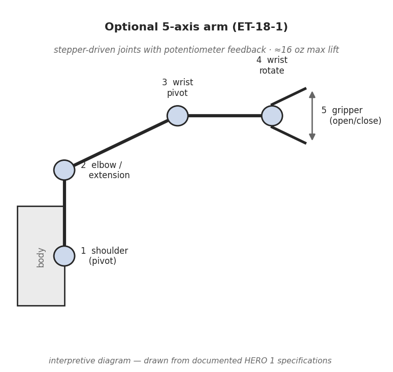
The secondary record is consistent that the arm’s motions are produced by stepper motors at the joints — the HERO FAQ describes the arm in terms of steppers driving the shoulder, wrist, rotation, pivot, and the gripper. A natural way to read five axes plus a grip onto a small arm of this kind is:
- a shoulder axis that raises and lowers the arm relative to the head;
- an extension or elbow axis that reaches the hand nearer or farther;
- a wrist axis that tips the hand up or down;
- a wrist-rotate axis that rolls the hand about its own line; and
- the gripper open/close as the end effector.
That breakdown is offered only as an interpretation — a plausible mapping of a small five-axis arm onto familiar joint names. It is not a documented joint map. The firm fact is “five axes plus a gripper” (HERO FAQ); the precise joint naming, order, travel ranges, and which axis is driven by which stepper are not asserted here. A reader who needs the authoritative kinematics should consult the ET-18-1 arm manual in the ET-18 manual set, which documents the arm’s mechanism exhaustively.
4.2.3 Stepper drive with potentiometer feedback
The arm’s control scheme is the most engineering-significant documented fact about it: the joints are driven by stepper motors and read by potentiometers (HERO FAQ). That pairing is the heart of how the arm holds and hits a position.
A stepper motor moves in fixed angular increments, one step per drive pulse, so a controller can position a joint open-loop simply by counting pulses — no encoder required for ordinary moves. But open-loop stepping has two weaknesses on a battery-powered arm carrying a load: if the motor misses steps (stalls against an over-heavy object or a mechanical limit), the controller’s pulse count no longer matches the joint’s true angle; and after a power cycle the controller has no idea where the joints actually are. The potentiometer on each joint closes that gap. A pot geared to the joint produces a voltage proportional to the joint’s angle, so the 6808 — reading those voltages through the robot’s I/O — always has an absolute measurement of where each axis really is, independent of the step count. The steppers supply precise incremental motion; the pots supply absolute position sensing and a way to detect when a commanded move did not land where it should. This is the same feedback philosophy that lets the teaching pendant record and replay arm motions (Vol. 7): the pendant can capture joint positions because the joints are continuously measured.
This also ties the arm back to the rest of the machine. The steppers are part of the “seven stepper motors control all movements” count (HERO FAQ); the consistent — but interpretive — reading is that several of those seven serve the arm, with the remainder driving the head rotation and the front-wheel steering (Vol. 3). The arm therefore shares the HERO 1’s basic actuation vocabulary: steppers for motion, sensors for feedback, the 6808 in the loop.
4.3 What the arm could — and couldn’t — do
The arm’s purpose was to let the HERO 1 reach into and rearrange its immediate environment — to pick up, hold, carry a short distance, and set down a light object. The published demonstration is exactly that: a HERO 1 using its gripper to hold a piece of food to a caged animal, shown in Figure 2. That photograph is a fair statement of the arm’s working envelope — a small, light object held in the gripper at the end of the extended arm.
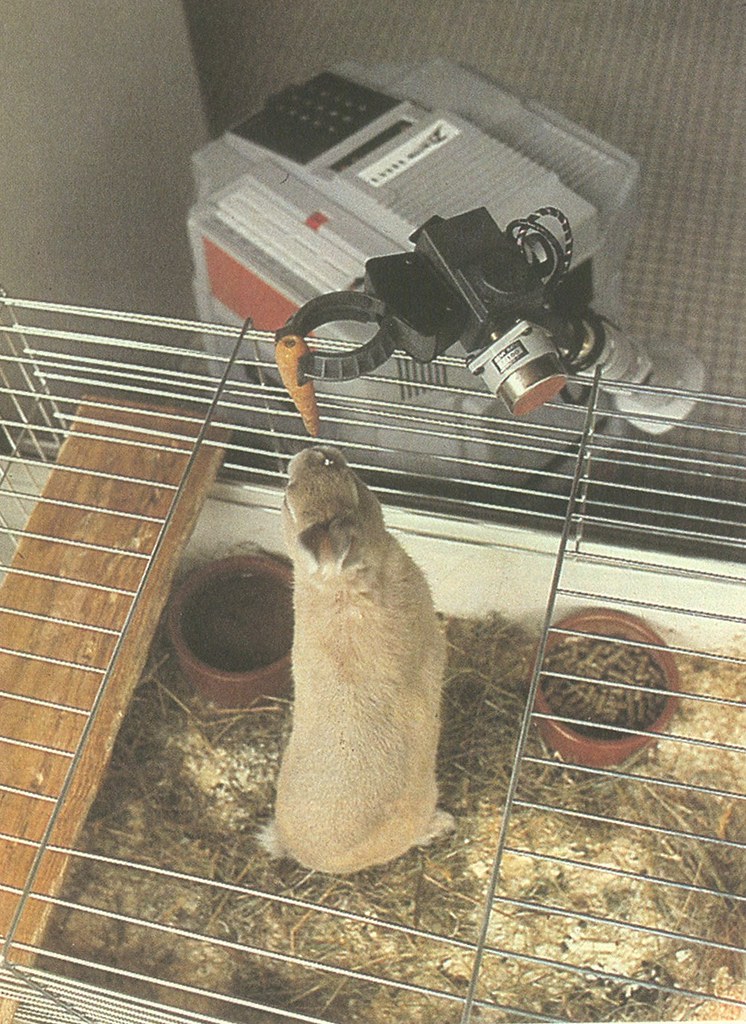
The hard limit on all of this is the lift figure: about 16 oz — one pound — is the maximum the arm could raise (HERO FAQ). That ceiling defines what “a light object” means in practice. A pound is a piece of fruit, a small tool, a light box, a cup — not a full bottle, not a book, not anything that would tax a one-pound arm reaching out from a 39-pound robot. The figure is a lift ceiling, and it should be read as such: a documented maximum, with real working loads well under it once the leverage of an extended arm and the modest torque of small stepper joints are taken into account.
It is consistent with the machine’s whole reason for existing that the arm was a teaching manipulator, not a working one. The HERO 1 was sold to the education and entertainment markets and, in the words of the record, “could not accomplish practical tasks” (Wikipedia; Vol. 1). The arm is a faithful instance of that: it demonstrates pick-and-place, grip, reach, and feedback control on a real five-axis mechanism a student could program — and it does so within a one-pound, table-top envelope that makes plain it was never meant to do industrial work.
Two cautions on the limits, in keeping with gating to the record. First, the arm’s reach — how far it could extend from the head — is not a figure asserted here; the documented quantitative limit is the ~16 oz lift, and the reach is left to the ET-18-1 arm manual. Second, the interpretive joint reading above is not a specification; anyone wanting exact joint travels, gear ratios, or the stepper-to-axis assignment must go to the arm manual in the ET-18 manual set rather than rely on the plausible mapping sketched here.
4.4 Where this fits
The head and the arm are the HERO 1’s actuated “front end,” and they lean on the volumes around them:
- Vol. 3 (Drive & Locomotion) covers the seven-stepper motion system as a whole — the head rotation and the arm joints draw their steppers from that same count, while the base’s propulsion and steering are the DC-motor exception.
- Vol. 5 (Sensing) covers the sonar, light, sound, and motion sensors that ride on the very head this volume describes; the head’s 350° pan is what aims that sensor cluster, exactly as it aims the arm.
- Vol. 7 (Programming & Control) covers how a program — or the teaching pendant — actually commands these motions, including the record-and-replay model that the arm’s potentiometer feedback makes possible.
Together they describe a robot that aims with its head, senses through that same head, and — when the ET-18-1 arm is fitted — reaches out to touch its world with a five-axis, stepper-driven, pot-sensed manipulator good for about a pound.
Comments (0)