Heathkit HERO 1 (ET-18) · Volume 5
Sensing — Sonar, Light, Sound, and Motion
5.1 Why a teaching robot needed senses
The HERO 1 was sold as a platform for learning robotics, circuitry, and the
rudiments of artificial intelligence (Wikipedia, “HERO (robot)”). None of that is
teachable on a machine that only moves; the lesson lives in the loop between
sensing the world, deciding what to do, and acting on the decision. The
HERO 1 was built to make that loop concrete and inspectable. Its sensor suite —
an ultrasonic ranging sonar, a light detector, a sound detector, and a motion
detector, supplemented by limit switches, a real-time clock, and an experimental
breadboard — gave a student program something to read, and the head, arm, and
drive train (Vols 3 and 4) gave it something to do in response (Wikipedia;
hero.dsavage.net HERO FAQ; theoldrobots.com).
This volume catalogs each documented sensor and the range or band it covered, gates every figure to a named source, and describes the role each plays in a sense→decide→act loop. How a program physically reads these sensors — which monitor registers it polls, how a BASIC or machine-code routine waits on the sonar — is the subject of Vol 7; this volume stops at what the hardware could detect and why each detector mattered.
5.2 The documented sensor suite
The HERO 1’s sensors and their published ranges are consistent across the
principal secondary sources — Wikipedia’s “HERO (robot)” article and the
hero.dsavage.net HERO FAQ agree on all four primary detectors, and
theoldrobots.com adds the supporting elements. The table below lists each with
its documented figure and the source that carries it; the rest of this volume
takes them one at a time.
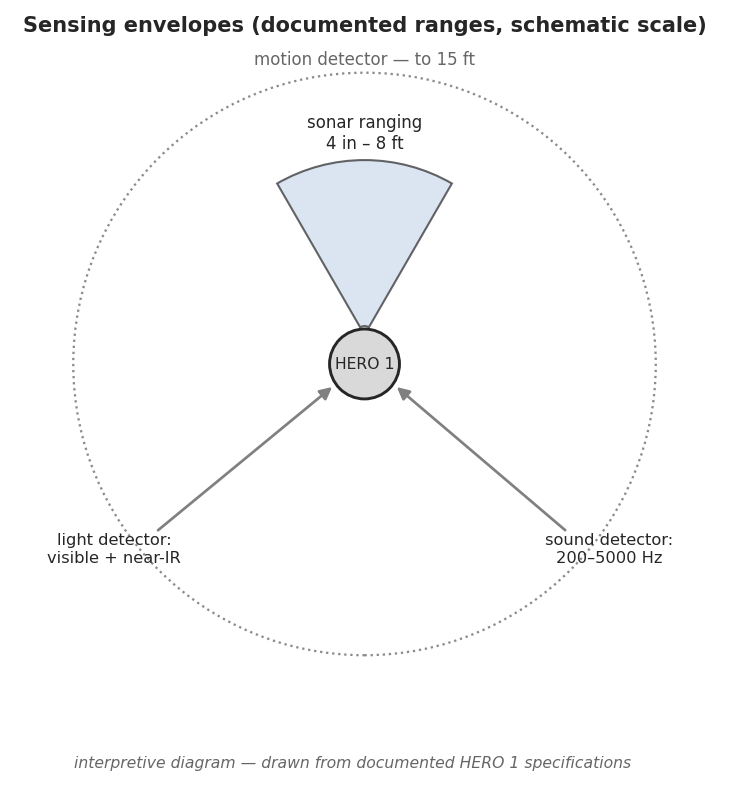
Table 1 — The documented sensor suite
| Sensor | Documented range / spec | Source |
|---|---|---|
| Ultrasonic ranging sonar | 4 inches to 8 feet | Wikipedia; HERO FAQ; theoldrobots.com |
| Light detector | Visible spectrum into the infrared | Wikipedia; HERO FAQ |
| Sound detector | 200–5000 Hz | Wikipedia; HERO FAQ |
| Motion detector | Up to 15 feet | Wikipedia; HERO FAQ |
| Limit switches | Travel-limit / end-of-motion sensing (no published range) | theoldrobots.com |
| Real-time clock | Onboard time reference (no published spec) | theoldrobots.com |
| Experimental breadboard | Solderless area for adding the experimenter’s own sensors | theoldrobots.com |
The exact transducer part numbers, the sonar’s operating frequency, and the beam angles of any of these detectors are not given in this record and are not asserted here. A reader needing the device-level specifics — the ranging circuit, the photodetector type, the audio passband components — should consult the ET-18 Technical Manual in the factory manual set, which carries the schematics; this volume reports only the figures the secondary sources document.
5.3 Ultrasonic ranging — 4 inches to 8 feet
The headline sensor is the ultrasonic sonar. It measures the distance to the nearest obstacle in front of the head, reporting a range from a documented minimum of 4 inches out to 8 feet (Wikipedia; HERO FAQ; theoldrobots.com). Below the minimum the target is too close for the round-trip echo to resolve; beyond the maximum the returning echo is too weak to register. Within that window the sonar is the HERO 1’s primary spatial sense — the one detector that returns a number, a range, rather than merely the presence or change of a stimulus.
In a sense→decide→act loop the sonar is what lets the robot avoid walls and furniture and what lets it find an object to approach. A program turns the head to aim the transducer (see “Aiming the cluster,” below), reads the range, and branches: if the range is short, stop or steer away; if a target sits at an expected distance, advance the drive wheel toward it (Vol 3 covers the drive). The 4-inch near limit matters for the arm work of Vol 4 — the gripper reaches past the point where the sonar can still resolve range, so close manipulation relies on the arm’s own potentiometer feedback rather than on sonar, while the sonar handles the approach.
The operating frequency of the transducer, its beam width, and its make are not documented in this secondary record and are left unclaimed. The figure that is firm is the 4 in–8 ft ranging window, agreed by all three sources cited above.
5.4 Light detection — the visible spectrum into the infrared
The light detector responds across the entire visible spectrum and into the infrared (Wikipedia; HERO FAQ). Its job is to register light level and light change: a program can have the HERO 1 react to a room’s lights being switched on or off, follow a bright source, or wake on a change in illumination. Because its sensitivity reaches past visible red into the infrared, it can also respond to near-IR sources a human eye would not see — the kind of source a TV remote or a warm lamp emits.
In the loop, the light detector is a low-rate ambient sense: it does not measure distance the way the sonar does, but it tells a program what the lighting is doing. A demonstration program might rotate the head until the light reading peaks (turning the robot’s “eye” toward the brightest part of the room), then act on that bearing. The specific photodetector device and the exact long- wavelength cutoff of its infrared response are not documented here and are not claimed; the gated fact is the qualitative band — visible through into the infrared.
5.5 Sound detection — 200 to 5000 Hz
The sound detector responds to audio in the band from 200 Hz to 5000 Hz (Wikipedia; HERO FAQ). That range is well matched to its likely use: it spans the bulk of speech and of the everyday sounds — claps, voices, household noises — that a teaching demonstration would use to trigger the robot. The lower bound at 200 Hz sits above most low-frequency room rumble; the 5 kHz upper bound covers the speech consonants and clap transients that make a useful trigger without extending into the ultrasonic.
As a loop input the sound detector is an event sense rather than a measuring one: it reports that a sound occurred (and, within its band, that the robot heard it), letting a program wake or respond on a clap or a spoken command’s acoustic energy. It is the natural companion to the optional Votrax SC-01 speech output of Vol 6 — a HERO 1 program could be written to listen, then answer in synthesized speech, closing a crude conversational loop. The detector senses the presence of in-band sound; it is not documented as performing pitch measurement or recognition, and no such capability is claimed here beyond the 200–5000 Hz passband the sources give.
5.6 Motion detection — up to 15 feet
The motion detector senses movement at a range of up to 15 feet (Wikipedia; HERO FAQ) — a longer reach than the sonar’s 8-foot ranging limit, but a different kind of reading. Where the sonar measures distance to a static surface, the motion detector reports that something in the room is moving, across a span of roughly 15 feet. It does not return a range; it returns the fact of motion within its field.
This is the HERO 1’s “someone just walked in” sense. In a sense→decide→act loop it serves as a trigger and an attention-director: a program can sit idle until the motion detector fires, then turn the head to bring the sonar and light detector to bear on whatever moved, then range it with the sonar and act. That hand-off — motion detector raises an alert, head swings, sonar measures — is exactly the kind of multi-sensor sequence the platform was built to teach. The detector’s underlying technology (whether passive infrared, ultrasonic Doppler, or otherwise) is not specified in this record and is not asserted; the documented figure is the 15-foot detection range.
5.7 The supporting sensors
Three further sensing elements round out the suite (theoldrobots.com). They have no published range figures, but each plays a defined part in the loop.
5.7.1 Limit switches
Limit switches are mechanical end-of-travel sensors. They report when a moving part — a steered wheel, a head rotation, an arm joint — has reached the end of its allowed range. Their role in the loop is proprioceptive rather than environmental: they protect the mechanism and give the monitor a known reference (“the head is at its rotation stop”), so that motion commands do not drive a joint past its limit. They complement the arm’s potentiometer position feedback of Vol 4, which measures position continuously, where the limit switches simply mark the extremes.
5.7.2 Real-time clock
The HERO 1 carries a real-time clock — an onboard time reference
(theoldrobots.com). For a sense→decide→act machine, time is itself a sensed
quantity: a program can schedule actions, wait a measured interval, or time how
long a condition persists. The clock is what makes “do X after N seconds” or
“patrol on a schedule” possible. Its specific resolution and the device used are
not documented here. (Distinct from this real-time clock is the monitor’s
1024 Hz timing counter at $0EFC noted in Vol 2 — a software-readable counter
rather than the wall-clock peripheral; the two should not be conflated.)
5.7.3 The experimental breadboard
The platform includes an experimental breadboard — a solderless prototyping area for the experimenter to add circuits of their own (theoldrobots.com). This is the clearest statement of the HERO 1’s teaching intent: the sensor suite was not meant to be the limit of what the robot could perceive, but a starting set that a student could extend. A builder could wire a new sensor onto the breadboard, read it through the robot’s I/O, and fold it into the same sense→decide→act loop the factory sensors used. The specific signals brought out to the breadboard are documented in the ET-18 Technical Manual rather than in this secondary record.
5.8 Aiming the cluster — the 350-degree head
The four environmental detectors share one decisive advantage: they are mounted together on the head, and the head rotates through 350 degrees (HERO FAQ; Wikipedia; theoldrobots.com). That single rotating axis turns a fixed, forward-looking sensor set into a steerable one. Without moving the drive base, a stationary HERO 1 can sweep its sonar, light detector, sound detector, and motion detector through nearly a full circle, building up a picture of its surroundings by bearing. The head is covered as a mechanism in Vol 4, and the stepper axis that turns it among the “seven stepper motors” of the platform is discussed in Vol 3; what matters for sensing is the consequence: the sensors all aim together.
This is what makes the multi-sensor sequences above practical. The motion detector fires; the program rotates the head toward the disturbance; now the sonar and light detector — having turned with the head — are aimed at the same bearing and can range and assess it. The 350-degree span (just short of a full 360 so the head has defined rotation stops, guarded by limit switches) gives near-complete coverage from a single position. Aiming the cluster is therefore not a separate sensor but the geometry that lets the sensors the HERO 1 has cover the room.
5.9 The loop, and where reading the sensors is covered
Put together, the suite gives a HERO 1 program a small but genuine set of senses: range from the sonar, illumination from the light detector, in-band sound from the sound detector, movement from the motion detector, mechanical limits from the switches, and time from the real-time clock — all aimable through 350 degrees of head rotation, and all extensible through the breadboard. A teaching program reads those inputs, decides on a branch, and drives the head, wheels, arm, and voice of Vols 3, 4, and 6 in response. That is the sense→decide→act loop the HERO 1 was built to make visible.
The mechanics of reading the sensors from a program — the monitor’s role, the registers a routine polls, the keypad and BASIC paths for writing the sense-decide-act code — are the subject of Vol 7, “Programming & Control.” The device-level circuit details behind each range figure given here live in the ET-18 Technical Manual of the factory manual set. This volume has reported only what the HERO 1 could sense, the documented band or range of each detector, and the role each plays in the loop.
Comments (0)