Heathkit HERO 1 (ET-18) · Volume 8
Acquisition, Restoration & Interfacing Today
8.1 What a HERO 1 is on the collector market
The HERO 1 reaches today’s collector as a roughly forty-year-old educational robot built in two factory forms: the solder-it-yourself kit (ETW-18) and the factory-assembled unit (ET-18) (HERO FAQ; Wikipedia, “HERO (robot)”). Because Heathkit sold on the order of 14,000 units over the line’s roughly eight-year run and supported the HERO family until 1995, surviving examples are uncommon but not vanishingly rare — the machine was produced in quantity and was, by design, documented well enough that owners kept and serviced them (Wikipedia). A HERO 1 on the market today is therefore a known quantity in its broad strokes; what varies, and what a prospective owner must read carefully, is which HERO 1 a given unit is and what condition its subsystems are in.
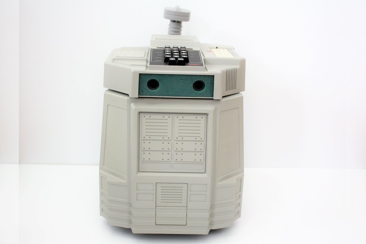
The first question is configuration. The base robot is the three-wheeled, 6808-controlled mobile platform with the sonar, light, sound, and motion sensors and the hex keypad on its head (covered in Vols 2, 3, and 5). On top of that base, the HERO 1 accepted a stack of factory options, each with its own manual and in several cases its own ROM: the five-axis arm (ET-18-1), the Votrax SC-01 speech board (ET-18-2), the RF remote (ET-18-3), the Utility/Demo ROM (ET-18-4), the memory-expansion board (ET-18-6), the Automatic Mode ROM (ET-18-7), and HERO-1 BASIC (ET-18-9), which itself required the expansion (HERO FAQ; the ET-18 manual set). A unit’s value and usefulness as a study machine depend heavily on which of these are fitted and intact. An arm-equipped HERO 1 with working speech is a markedly more complete specimen than a bare base unit, and the arm and the Votrax board are exactly the parts most likely to be missing, swapped, or damaged after four decades.
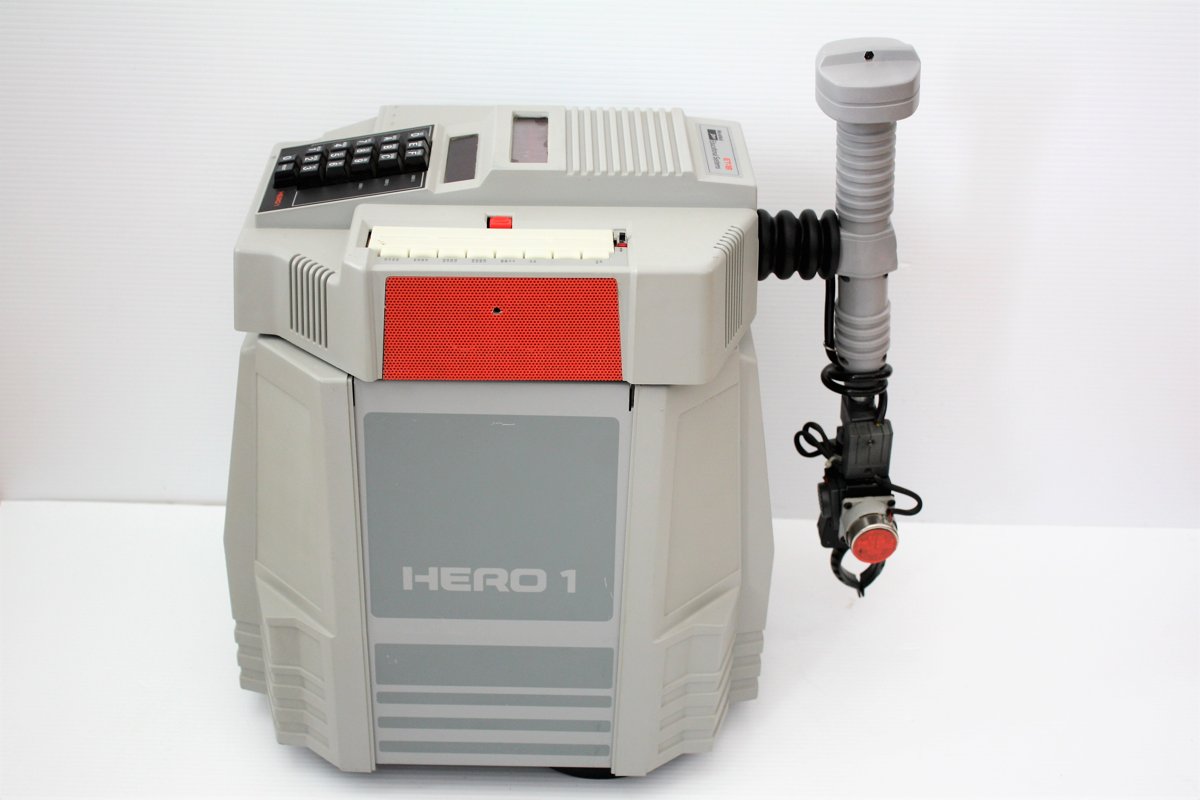
The second question is completeness of the accessories that did not bolt to the robot: the teaching pendant, the RF remote transmitter (offered in two frequency models), the charger, and the printed manuals. A HERO 1 separated from its pendant and charger is still a HERO 1, but reuniting it with period-correct control accessories is part of what restoration entails. None of these are reproduced here as price or rarity figures — the collector market for a low-volume 1980s educational robot is thin and anecdotal, and this volume makes no claim about what any given unit is worth or how scarce a given option is.
8.2 The manual set is the restorer’s primary resource
The single most important fact for anyone acquiring a HERO 1 is that its
documentation survives and is freely downloadable. The complete factory ET-18
manual set is hosted on the Internet Archive
(archive.org/details/heathkit-hero-1-ET-18). Heathkit’s whole business was the
documented kit, and the HERO 1 was documented to that standard: every subsystem
shipped with a manual written to walk a non-expert through assembly, theory, and
operation. For a restorer this is decisive — the machine can be taken apart and put
back together against the original instructions rather than reverse-engineered.
The set a restorer reaches for most often:
Table 1 — The set a restorer reaches for most often
| Manual | Designation | What it covers | Source |
|---|---|---|---|
| Assembly Manual | ET-18 | Step-by-step build of the base robot — drive train, sensor boards, 6808 system | ET-18 manual set |
| Technical Manual | ET-18 | Theory of operation, schematics, and the full memory map | ET-18 manual set |
| Arm | ET-18-1 | The optional five-axis arm and gripper | ET-18 manual set |
| Voice / Speech | ET-18-2 | The optional Votrax SC-01 speech board | ET-18 manual set |
| Remote Operation | ET-18-3 | The optional RF remote control | ET-18 manual set |
| HERO-1 BASIC | ET-18-9 | The BASIC interpreter ROM (requires memory expansion) | ET-18 manual set |
Two further documents matter for the work this volume describes. The Technical Manual carries the schematics and the exhaustive memory map; it is the reference for any board-level diagnosis and is the document Vol 2 defers to for the complete address map rather than reconstructing it. And the memory-expansion documentation (ET-18-6) is the route to the RS-232 host link discussed below. The Utility/Demo ROM (ET-18-4) and Automatic Mode ROM (ET-18-7) round out the accessory set (HERO FAQ; the ET-18 manual set). A restorer’s first action on acquiring a unit should be to download the matching manuals and identify exactly which boards and ROMs the robot in hand actually contains.
8.3 Common aging concerns
The following are the subsystems that age, described qualitatively and attributed. This volume invents no failure rates, no service-life figures, and no prices — those are not in the documented record, and the specific condition of any forty-year-old robot is an empirical question to be answered with a meter and an inspection, not a statistic.
8.3.1 The battery pack
The HERO 1 carries an internal pack of four gel-cell rechargeable batteries, replenished by an included 120/240 VAC, 50/60 Hz charger (HERO FAQ; theoldrobots.com). Gel cells are a sealed lead-acid (VRLA) chemistry, and the hub safety page treats the HERO 1’s pack explicitly as a sealed lead-acid (SLA) pack. This is the single most likely subsystem to need attention on acquisition: rechargeable lead-acid cells do not survive decades of storage in a usable state, and a pack that has sat discharged is almost certainly spent.
Before touching the battery pack or the charger, consult _shared/safety.md.
Per the hub’s posture, any restoration step involving the battery or the
mains charger must be read against that page first. Its directly relevant
cautions, in brief: old SLA cells can leak acid and can deliver very high
short-circuit current — a dead short across the pack can weld tools and start a
fire, so the pack should be fused, its terminals never shorted, and leaking cells
disposed of properly; the mains-side charger wiring should be treated as live,
unplugged before any internal work and verified with a meter, with cracked line
cords and failed strain reliefs replaced; and charging should be done on a
non-flammable, ventilated surface, attended (_shared/safety.md). Replacement of
a spent pack with cells of the documented configuration is the routine path; this
volume does not specify a part number or capacity, both of which belong to the
ET-18 Technical Manual and the cells actually fitted.
8.3.2 Stepper and drive-train wear
The HERO 1’s motion comes from a DC-motor front drive and seven stepper
motors controlling its other movements — steering, the 350° head rotation, and
the arm axes (HERO FAQ; the precise allocation is treated as interpretive in Vol
3). Mechanical wear is the expected failure mode here rather than electronic
failure: decades-old grease stiffens, the front drive-and-steer assembly that
carries the robot’s weight is a wear point, and the stepper-driven joints — in
particular the arm, with its potentiometer position feedback — can develop slop,
binding, or noisy pots. None of this is quantified in the secondary record; a
restorer evaluates it by exercising each axis under the manual’s diagnostic
guidance and watching for missed steps, binding, or feedback that no longer tracks.
The safety page’s mechanical cautions apply throughout: arms, grippers, and drive
motors pinch and crush, and power should be removed before reaching into any
mechanism (_shared/safety.md).
8.3.3 The hex-keypad membrane
The robot’s primary human interface is the 17-key hexadecimal keypad and six-digit seven-segment LED display set into the head, used to enter, verify, and modify programs and to select operating modes (Wikipedia; HERO FAQ). A membrane keypad of this age is a known wear item on vintage equipment generally — the tactile domes and the printed conductive traces degrade with use and time, producing dead or intermittent keys. The HERO 1 record does not document a specific failure mode or rate for this part, so it is flagged here only as a subsystem a restorer should exercise key-by-key against the keypad functions described in Vol 7, and one whose condition bears directly on whether the robot can be programmed from its own head at all.
8.4 Modern interfacing paths
The most useful fact for bringing a HERO 1 back into service alongside modern equipment is that the factory already provided an external-control route. The memory-expansion board (ET-18-6) carries an RS-232 interface, and that serial link is the documented path for connecting the robot to a host (HERO FAQ). This matters today because RS-232 is still trivially bridged to a current computer with a USB-to-serial adapter, which makes the ET-18-6 link the natural, period-correct way to talk to a HERO 1 from a modern machine rather than driving everything from the hex keypad. The host link is described as a control route in Vol 7; this volume’s point is narrower — that the serial interface is the documented, supported interfacing path, and a unit fitted with the ET-18-6 expansion is the more straightforward one to integrate with modern gear.
The same expansion board is the prerequisite for HERO-1 BASIC (ET-18-9), which requires the added memory (HERO FAQ; the ET-18 manual set). A restorer interested in programming the robot in BASIC rather than 6808 machine code is therefore looking for the same board that enables the serial host link — the two capabilities ride on the one option. Where a unit lacks the expansion, programming remains the keypad machine-code path described in Vol 7, and external control reverts to the RF remote (ET-18-3) and teaching-pendant routes rather than a serial host.
Beyond the documented RS-232 path, the HERO 1’s openness — a single 6808 bus, memory-mapped I/O, and an experimenter’s breadboard area provided on the robot itself (theoldrobots.com) — is what made it a teaching machine, and it is what makes modern reinterfacing feasible at all. This volume stops at the documented: the supported external-control route is the ET-18-6 RS-232 link. Any deeper modern modification — substituting a microcontroller for an aged subsystem, emulating a missing board, or replacing the battery management — is real restoration practice but is not in the HERO 1 documentary record, and is left explicitly unclaimed here. The starting point in every case is the same: the freely available ET-18 manual set, read against the actual hardware, and the safety page read before any battery or mains work.
8.5 Where this sits
This volume closes the deep dive on the practical question of owning the machine
the earlier volumes describe. The base platform and power are detailed in Vol 2;
the drive and the seven steppers in Vol 3; the head and arm in Vol 4; the sensor
suite in Vol 5; the Votrax speech in Vol 6; and the four control routes — keypad,
pendant, remote, and the RS-232 host — in Vol 7. The cheatsheet, Vol 9, gathers
every hard number with its source. For acquisition and restoration specifically,
two resources govern the work: the ET-18 manual set on the Internet Archive as
the technical authority, and _shared/safety.md as the standing precondition
for any battery, charger, or powered-mechanism step.
Comments (0)