Heathkit HERO 1 (ET-18) · Volume 3
Drive & Locomotion — Three Wheels, a DC Drive, and Seven Steppers
3.1 The locomotion problem a teaching robot has to solve
A mobile robot has to move its whole mass across a floor, change heading on command, and report back to its program where it went — all from a battery pack it also has to carry. The HERO 1 solves this with a deliberately simple running gear: three wheels — two fixed at the rear and one steerable drive wheel at the front — powered and steered by DC motors, with stepper motors handling the precise, repeatable motions elsewhere on the machine (HERO FAQ; theoldrobots.com). The result is a platform a student can both build and reason about: the drive train is conventional enough to understand at a glance, yet instrumented enough that a 6808 program can command motion and read back position.
This volume covers the base and how the robot drives and steers it. The 350°
rotating head — which shares the “aiming” job with the drive but is mechanically
separate — is examined alongside the optional arm in Vol. 4, and the sensors that
the head aims are in Vol. 5. The memory-mapped registers a program writes to
command motion (the documented $0000 “Extend” and $0006 “Steering” landmarks)
belong to the architecture and programming volumes (Vols. 2 and 7); this volume is
about the mechanism those registers drive.
3.2 The three-wheel base
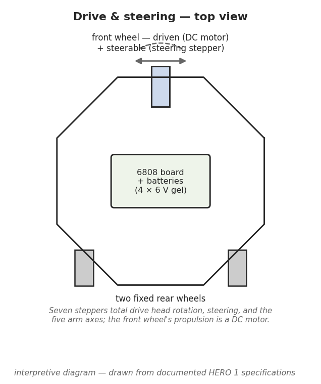
3.2.1 Layout: two fixed rear wheels, one steerable front
The HERO 1 rolls on three wheels. Two are fixed at the rear and carry no steering or drive function of their own; the single front wheel does both jobs — it is the steerable drive wheel (HERO FAQ). This is the classic tricycle configuration, and it is the simplest arrangement that gives a robot full mobility on a flat floor: the two passive rear wheels provide a stable base of support, and all of the “active” locomotion — push and turn — concentrates at one driven, steered wheel up front.
The tricycle choice has direct consequences for how the robot behaves, and they are worth stating because they shape every program written for it:
- Turning is coupled to driving. Because the same front wheel both pushes and points, the robot changes heading by steering the front wheel and rolling forward, the way a child’s tricycle turns — not by spinning two independently driven wheels against each other (a differential, or “tank”, drive). A HERO 1 does not pivot in place around its own centre the way a differential-drive robot can; it follows a curved path set by the steering angle.
- The rear axle is dead simple. With no drive or steering hardware at the back, the two rear wheels are just rolling supports. That keeps mass, cost, and failure points down — appropriate for a kit a student solders together.
- One wheel carries the whole drive system. Everything that makes the robot go — motor, steering, and the feedback that tells the program where the wheel is pointed — is packed into the front assembly.
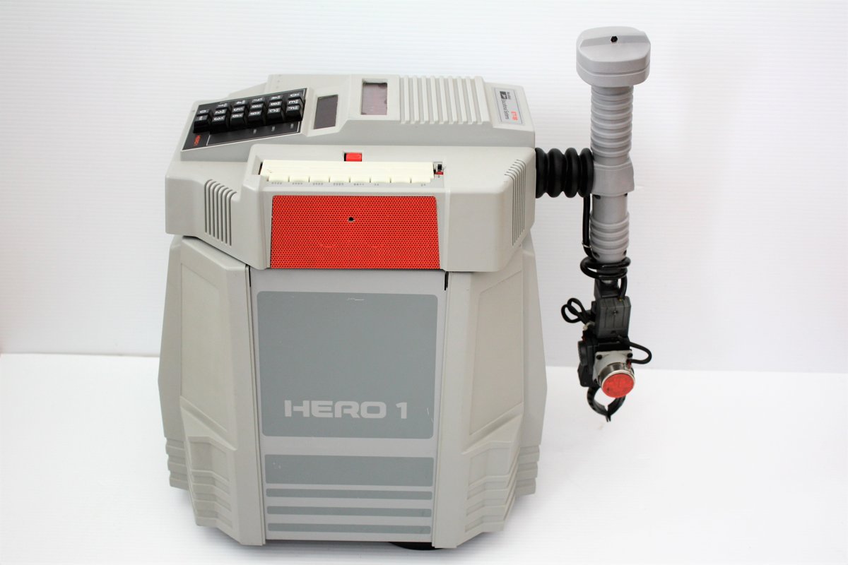
The base sits under the segmented outer shell of a machine that stands 20 inches high, measures 18 inches in diameter, and weighs about 39 pounds with its accessories fitted (HERO FAQ; theoldrobots.com). That 39-pound figure is the load the front wheel’s DC drive has to start, move, and stop — and the reason the drive motors are described as “powerful” in the secondary record (HERO FAQ).
3.2.2 Why a tricycle, and not tracks or four wheels
For a 1982 educational robot, the steered-front-wheel tricycle is a sound engineering compromise. Tracks give traction and let a machine turn in place, but they are heavy, draw more power, scuff floors, and are harder for a kit-builder to assemble and maintain. Four driven wheels demand either steering linkages or a slip-steer scheme, both more complex. Three wheels with one doing the work is the minimum mechanism that still lets the robot go anywhere on a flat indoor surface — which is exactly the world the HERO 1 was built to explore. The trade is manoeuvrability: the HERO 1’s turning is path-following, not pivot-in-place, and a program has to account for the curve a steered tricycle traces.
3.3 Propulsion and steering: DC motors at the front wheel
3.3.1 A DC drive, not a stepper drive
The HERO 1’s road motion is DC-driven. The secondary record is explicit and consistent on this point: “powerful front wheel DC motors drive and steer HERO 1” (HERO FAQ; theoldrobots.com). Both functions at the front wheel — pushing the robot along (propulsion) and pointing the wheel (steering) — are handled by DC motors, not by the stepper motors used elsewhere on the machine.
That division of labour is a considered one, and it reflects what each motor type is good at:
- A DC motor is the right tool for propulsion. It delivers smooth, continuous torque, runs efficiently at the speeds and loads of driving a ~39-pound robot across a floor, and is happy being driven hard from a battery. What a plain DC motor does not give you for free is precise knowledge of how far it has turned — so the robot adds position feedback (below) rather than swapping in a different motor type.
- A stepper motor is the right tool for repeatable positioning — moving a known number of discrete steps and holding there. Steppers are how the HERO 1 gets exact, repeatable motion on the axes that need it (covered next), but they are a poor choice for sustained road speed, where their torque falls off and they offer no advantage over a cheaper, smoother DC motor.
So the HERO 1 splits the work by physics: DC for the continuous job of driving and steering the front wheel, steppers for the precise jobs elsewhere.
3.3.2 Closing the loop: the documented “Steering” register
A bare DC motor is open-loop — energise it and it spins, but it does not tell you
where it ended up. For steering, that is unacceptable: a program that says “point
the wheel straight ahead” has to actually get the wheel straight, every time. The
HERO 1 therefore reads the steering position back to the processor. The HERO FAQ’s
partial memory map documents a $0006 “Steering” register holding a value in the
range 00–93 — a numeric encoding of steer position that the 6808 monitor can read
and write (HERO FAQ). The exhaustive description of how that register maps to a
physical wheel angle, and the electrical details of the feedback element, live in
the ET-18 Technical Manual; this volume gates only to the documented fact that a
steering position is represented as a software-readable value in the 00–93
range and does not reconstruct the conversion.
The companion landmark is the $0000 “Extend” register (range 00–98) (HERO
FAQ). It is treated as part of the motion-command surface in the architecture and
programming volumes (Vols. 2 and 7) rather than asserted here as a specific drive
quantity; what is documented is its existence and its 00–98 range, not a
mechanical meaning this volume would have to invent. Together, the two registers
illustrate the HERO 1’s control model: motion is commanded and sensed as numbers
in a memory map, so a program can both drive the robot and find out what the drive
actually did.
3.4 The seven stepper motors
3.4.1 What the record firmly states
The single hard fact about the HERO 1’s stepper complement is this: “seven stepper motors control all movements” (HERO FAQ). That is the claim this volume stands on. Combined with the DC drive, it gives the machine’s complete actuation inventory at the level the documented record supports it:
Seven stepper motors, plus a DC drive at the front wheel.
The steppers are what give the HERO 1 its precise, repeatable motions — the kind where a program needs to move an axis a known amount and trust that it arrived. As a class, stepper-driven joints on the machine are documented as carrying potentiometer position feedback (HERO FAQ), the same closed-loop philosophy seen at the steering wheel: command a motion, then read back where the mechanism actually went.
3.4.2 Where the seven steppers go — an explicitly interpretive note
It is tempting to itemise the seven motors, and the secondary record invites a natural reading — but the allocation is not cleanly itemised in the documented secondary sources, and is flagged here as interpretive. What follows is not asserted as documented fact:
- The head rotates 350° to aim the sensors and the arm (HERO FAQ; Wikipedia; theoldrobots.com); a stepper is the obvious mechanism for a repeatable angular axis, and the head is examined in Vol. 4.
- Steering the front wheel is documented as a DC function (above), not a stepper one — so the common assumption that “one of the seven steppers is the steering” runs against the explicit DC-steering statement in the record. This is exactly the kind of plausible-but-unverified split this volume refuses to assert.
- The optional arm (ET-18-1) has five axes plus a gripper, documented as stepper-driven with potentiometer feedback (HERO FAQ); five arm axes is the largest obvious consumer of steppers, and the arm is detailed in Vol. 4.
A widely repeated reading lines the seven up as roughly head rotation + the five arm axes + one more, but the exact split — which axes are stepper-driven, in what order, and whether steering or some base function is counted among the seven — is not something the secondary record itemises cleanly, and the DC-steering fact above complicates the tidiest versions of that count. The authoritative allocation is in the ET-18 Technical Manual’s drive and arm schematics. This deep dive therefore gates to the firm statement — seven steppers control the machine’s movements, and the front-wheel drive is DC — and leaves the precise motor-by-motor map explicitly unclaimed. The exact stepper allocation is not reconstructed here. Readers who need the definitive count should consult the ET-18 Technical Manual’s schematics directly.
3.4.3 Steppers vs. the DC drive, side by side
Table 1 — Steppers vs. the DC drive, side by side
| Motion | Motor type | Feedback | Source |
|---|---|---|---|
| Front-wheel propulsion (driving) | DC | — (continuous drive) | HERO FAQ; theoldrobots.com |
| Front-wheel steering | DC | Steering position value, $0006 range 00–93 | HERO FAQ |
| Head rotation (350°, aims sensors + arm) | Stepper (interpretive — see Vol. 4) | Position feedback (stepper class) | HERO FAQ; Wikipedia |
| Arm axes (optional ET-18-1: 5 axes + gripper) | Stepper (interpretive split — see Vol. 4) | Potentiometer position feedback | HERO FAQ |
| Stated total | Seven steppers + the DC drive | — | HERO FAQ |
The rows marked interpretive identify the likely stepper consumers; the table does not assert that they sum to exactly seven in the manner shown, because the record does not itemise the seven that cleanly. The one wholly firm line is the total: seven steppers plus the DC drive.
3.5 The head as the aiming axis
Although the head is the subject of Vol. 4, it belongs in any discussion of how the HERO 1 gets where it’s looking, because it shares the aiming job with the drive. The head rotates through 350° to point the sensor cluster and the arm mount (HERO FAQ; Wikipedia; theoldrobots.com). That nearly-full rotation matters for locomotion in a specific way: it decouples sensing direction from travel direction. A differential-drive robot that wants to look left usually has to turn its body left; the HERO 1, because its head can swing almost all the way around, can aim its sonar and detectors in nearly any direction while the base stays put — or while the base is mid-manoeuvre travelling a different way.
For a tricycle base whose turning is path-following rather than pivot-in-place, that is a real advantage. The robot does not have to drive a curve just to see to its side; it rotates the head. The 350° span (rather than a full 360°) reflects a mechanical stop or cable-routing limit — the documented value is 350°, and this volume does not speculate about the missing 10°. How the head’s rotation is driven, and how it carries the sensor cluster and arm, is the start of Vol. 4; how the sensors it aims actually work is Vol. 5.
3.6 Power and runtime — what can and can’t be said
Everything above runs on the robot’s own battery. The HERO 1 carries an internal pack of four gel-cell rechargeable batteries, replenished by an included 120/240 VAC, 50/60 Hz charger (HERO FAQ; theoldrobots.com). The robot is, by design, mains-independent in operation: it charges from the wall, then runs free on the floor. That is the whole point of a self-contained mobile robot — it has to take its energy with it.
Several things follow qualitatively, and only qualitatively, because the documented record does not state a battery capacity or a runtime figure, and this volume does not invent one:
- The drive is the heaviest electrical load. Starting and moving ~39 pounds across a floor with a DC motor is the most demanding thing the robot does electrically; a gel-cell pack is a sensible choice for that duty because it can deliver the surge current a drive motor draws on start-up.
- Runtime depends entirely on use. A HERO 1 parked and “thinking” sips power; a HERO 1 driving continuously, swinging its head, and working its arm drains the pack far faster. Without a documented capacity, no runtime number is asserted here — only the relationship that motion is what costs energy.
- Gel cells are sealed and rechargeable, which is why a charger ships in the
box rather than a recommendation to swap dry cells. The collecting and
restoration consequences of an aged gel-cell pack — the single most common issue
on a machine of this vintage — are taken up in Vol. 8, which also cross-references
_shared/safety.mdfor the gel-cell and mains-charger cautions.
The plan’s fact base flags one point of care on the batteries: theoldrobots.com gives “four gel cell,” and the 6 V per-cell value is widely reported but is not treated as fully nailed-down here. This volume therefore states the firm part — four gel-cell rechargeable batteries with a 120/240 VAC charger — and does not assert a pack voltage or amp-hour rating as documented fact. The exhaustive power specification belongs to the ET-18 Technical Manual and is summarised, to the extent the record supports it, in the architecture volume (Vol. 2).
3.7 Summary
The HERO 1’s locomotion is an exercise in matching the mechanism to the job. A
three-wheel tricycle base — two fixed rear wheels, one steerable front drive
wheel — gives a kit-buildable, easily-reasoned-about platform that can go anywhere
on a flat floor, at the cost of pivot-in-place agility (HERO FAQ). DC motors drive
and steer that front wheel, because a DC motor is the right tool for continuous
road motion, with the steering closed-loop through a software-readable position
value (the documented $0006 “Steering” register, range 00–93) (HERO FAQ;
theoldrobots.com). Seven stepper motors handle the machine’s precise, repeatable
movements, with potentiometer feedback on the stepper-driven joints — the one
firm statement being seven steppers plus the DC drive, with their exact
motor-by-motor allocation left explicitly to the ET-18 Technical Manual rather than
reconstructed here (HERO FAQ). The 350° head shares the aiming job, letting the
robot point its senses without driving a curve (HERO FAQ; Wikipedia). And all of it
runs from four gel-cell batteries off an included charger, with runtime left
qualitative because the record gives no capacity to quote (HERO FAQ;
theoldrobots.com). The head and arm that the steppers move are Vol. 4; the sensors
the head aims are Vol. 5; the registers a program writes to command all of this are
Vols. 2 and 7.
Comments (0)