Loofbourrow · Volume 2
The KIM-1 Brain — a 6502 Single-Board Computer in Command
2.1 Why a single-board computer
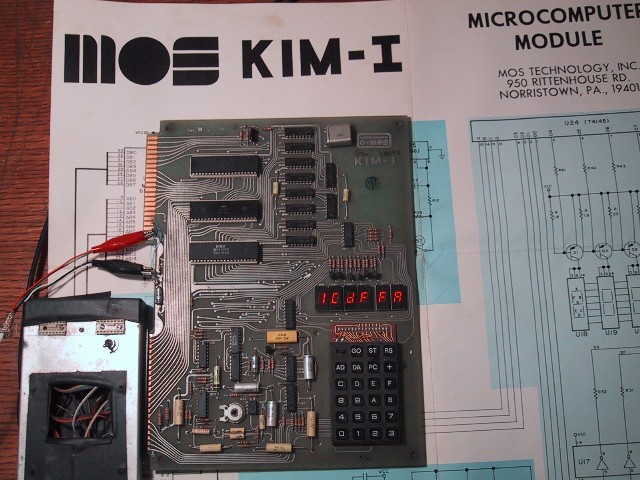
Embedding a microprocessor in a mobile robot in 1975 required a decision that most experimenters made by default: build a computer from discrete chips and wire, or find one ready-made. For Loofbourrow, the KIM-1 settled that question. As Chuck Peddle, the 6502’s chief designer, described the finished product: “It was a packaged, complete, plug-it-in-and-start-using-it product” (Bagnall, “Tim and Kim”). The board arrived assembled, documented to an unusual depth for its era, and capable of accepting a program and running it within minutes of receiving power. For a robot builder, that completeness eliminated an entire layer of the design problem.
The contrast with the Altair 8800 — released in the same year, 1975 — is instructive. The Altair “relied on switches for input and blinking lights for output. Any other interfaces had to be added by the user” (Bagnall, “Tim and Kim”). Writing a program for the Altair meant flipping binary switches row by row; reading results meant interpreting a row of LEDs as bit patterns. The KIM-1 provided a six-digit hexadecimal display and a 23-key keypad, which moved the human interface from pattern-reading to direct hex entry. Al Charpentier, a MOS Technology engineer who worked alongside the KIM-1’s development team, summarized the contrast tersely: “It was sort of the first fully packaged microcomputer that you could take out of the box, throw a power supply on, and do something with” (Bagnall, “Tim and Kim”).
As a single-board computer — all components on one printed-circuit board with no expansion slots required for basic operation — the KIM-1 also offered a pricing advantage that was real rather than theoretical. The Altair sold for $439 in kit form; the KIM-1 sold fully assembled for $245 (Bagnall, “Tim and Kim”). For a robot chassis that needed a brain and not a computer project unto itself, a self-contained board at that price was the practical choice.
2.2 Architecture
The KIM-1 was designed by John May under the direction of Don McLaughlin, MOS Technology’s founder and engineering manager for the project (Bagnall, “Tim and Kim”). The board is built around a MOS Technology 6502 microprocessor running at one megahertz. The 6502’s internal architecture — a relatively small but efficient instruction set, fast zero-page addressing, and a compact silicon die — allowed more work per clock cycle than competing 8-bit processors of the era. The robot’s assembly listings exploited this efficiency in the speed-control and steering routines; that code is examined in Vol. 7.
2.2.1 Memory
The KIM-1 provided one kilobyte of read/write memory, implemented as eight MOS Technology 6102 RAM chips (Bagnall, “Tim and Kim”). The capacity was understood at the time as the practical upper bound for a self-contained program on this class of hardware; the section “Living within the KIM-1,” below, returns to what that constraint meant for the robot’s code.
Supplementing the 6102 array were two MOS Technology 6530 RRIOT chips. Each 6530 integrated four functional blocks on a single die: a block of read/write RAM, a block of factory-programmed ROM, two 8-bit parallel I/O ports (designated PA and PB), and a programmable interval timer (Bagnall, “Tim and Kim”). The designation RRIOT — ROM, RAM, I/O, Timer — captures this multi-function role. By housing memory, I/O, and timing logic in the same package, the 6530 reduced chip count while providing the KIM-1 with the I/O infrastructure Loofbourrow’s robot would later use. The RAM areas inside the two 6530 chips were small but not zero; a contemporary programmer noted that they could serve as extra working storage when the main 1 KB was fully committed (Bagnall, “Tim and Kim”).
2.2.2 The TIM monitor
The ROM of the KIM-1’s 6530 RRIOTs held the machine’s monitor — a roughly 2-kilobyte program that Bagnall records was, like the earlier development kit, named TIM, the Terminal Interface Monitor (Bagnall, “Tim and Kim”). (The grey-ceramic 6530-004 that Bagnall describes was the chip supplied with the separate $30 TIM development kit, not a KIM-1 part; the part numbers of the KIM-1’s own 6530s are not given in the source.) TIM was originally written by Manny Lemas and Mike Quarter of Microcomputer Associates and subsequently adapted for the KIM-1 by John May, who reused the code that the TIM development kit had established (Bagnall, “Tim and Kim”). The monitor’s responsibilities included: driving the six-digit LED display, reading the 23-key keypad, operating the cassette-tape save and load routines, and managing the serial TTY interface. On every reset, a small bootstrap program started TIM automatically, presenting an address/data prompt on the display and waiting for keypad input (Bagnall, “Tim and Kim”). There was no boot sequence to navigate and no operating system to load.
A debugging aid of practical importance was the SST key. Labeling it “Single Step” on the keypad, the KIM-1 allowed an operator to press SST before GO and then watch the 6502 execute the loaded program one instruction at a time, pausing after each to allow memory and register inspection (Bagnall, “Tim and Kim”). For a robot program with tight timing relationships between motor commands and sensor reads, single-step tracing was the primary tool for diagnosing misbehavior.
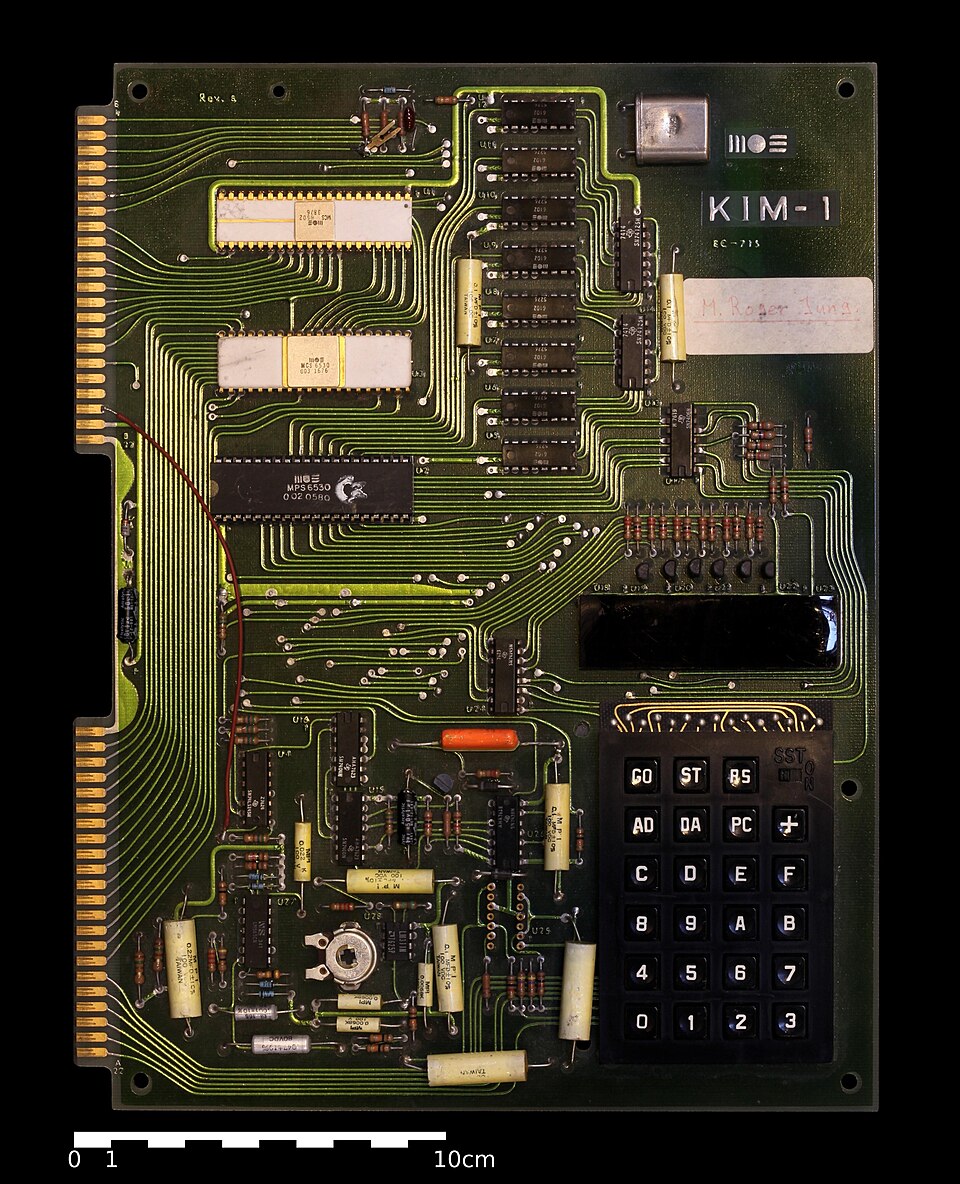
2.2.3 Human interface
The KIM-1 carried two on-board human-interface elements, both mounted directly on the printed circuit board:
- Six-digit seven-segment LED display. Each digit displayed a hexadecimal character (0–F), giving the operator a direct read of memory addresses and data bytes without a terminal. The TIM monitor used the display to echo the current address and data byte during entry; programs could write to the display for status output. The Interface Age listings for the robot used the display in this way (covered in Vol. 7).
- 23-key keypad. John May selected a black keypad with 23 buttons (Bagnall, “Tim and Kim”). Bagnall names three of them explicitly: RS (reset), which restarted the monitor; GO, which executed a program from a given address; and SST (single step), the debugging key. The keypad supported direct hexadecimal entry and was the primary programming interface — every byte of a program was keyed in as hexadecimal and verified on the display. The full complement of monitor-command keys is not enumerated in the available source and is not detailed here.
This combination — display plus keypad — distinguished the KIM-1 from machines that required a terminal for any useful interaction. For a robot operating away from a workbench, the self-contained interface meant that a programmer could inspect memory, patch a byte, and re-run a routine without any attached peripheral.
2.2.4 Storage and serial interface
The KIM-1 provided two data-exchange interfaces beyond the keypad. The first was a built-in cassette-tape interface: programs saved to and loaded from standard audio cassette, and the tape protocol was uniform across all KIM-1 units, so a cassette recorded on one board would load on any standard KIM-1 (Bagnall, “Tim and Kim”). The tape interface made program distribution practical among the KIM-1 hobbyist community and allowed a robot programmer to maintain multiple versions of the control code on separate cassettes.
The second interface was a serial port for teletype machines and ASCII terminals. A notable feature of the KIM-1’s serial implementation was its auto-baud detection: the board automatically adjusted to the speed of the connected device, sparing the operator manual baud-rate configuration (Bagnall, “Tim and Kim”). For the robot application, the serial port was less relevant than the cassette interface and the keypad, but it remained available for debugging sessions involving a terminal.
2.2.5 Expansion connectors
Two 44-pin edge connectors along the board’s long edge exposed the 6502 address bus, data bus, and control signals, together with I/O port lines and power connections, to external circuitry (Bagnall, “Tim and Kim”). John May designed the KIM-1 with expansion in mind from the outset (Bagnall, “Tim and Kim”). The Interface Age article labels the edge connector through which the robot reached the 6530’s PA port pins the “microprocessor connector” (Interface Age, Apr. 1977, Diagram D; see “The I/O the robot used,” below). The bus connectors also served as the mechanical and electrical interface for the KIM Modular System expansion products — memory boards, motherboards, and prototyping cards — developed by third parties after the KIM-1’s commercial success became apparent (Bagnall, “Tim and Kim”), though those expansion products were not part of Loofbourrow’s documented Stage I build.
2.2.6 Specification summary
Table 1 — Specification summary
| Specification | Value | Source |
|---|---|---|
| Processor | MOS Technology 6502 | Bagnall, “Tim and Kim” |
| Clock rate | 1 MHz | Bagnall, “Tim and Kim” |
| RAM (main) | 1,024 bytes — eight MOS Technology 6102 chips | Bagnall, “Tim and Kim” |
| Additional on-chip RAM | Small RAM areas in two MOS 6530 RRIOTs | Bagnall, “Tim and Kim” |
| ROM — monitor | TIM (Terminal Interface Monitor), ~2 KB, in 6530 ROM | Bagnall, “Tim and Kim” |
| I/O controller chips | Two MOS 6530 RRIOTs (ROM + RAM + I/O + timer, each) | Bagnall, “Tim and Kim” |
| Display | Six-digit seven-segment LED | Bagnall, “Tim and Kim” |
| Keypad | 23-key hexadecimal keypad | Bagnall, “Tim and Kim” |
| Debug key | SST (Single Step) | Bagnall, “Tim and Kim” |
| Storage | Built-in cassette-tape interface | Bagnall, “Tim and Kim” |
| Serial interface | Auto-baud TTY / teletype | Bagnall, “Tim and Kim” |
| Expansion | Two 44-pin edge connectors (bus + I/O) | Bagnall, “Tim and Kim” |
| Release price | $245 (fully assembled, minus power supply) | Bagnall, “Tim and Kim” |
| Release date | Mid-1975 | Bagnall, “Tim and Kim” |
| Power switch | None — RS (reset) key only | Bagnall, “Tim and Kim” |
| Principal designer | John May, under Don McLaughlin | Bagnall, “Tim and Kim” |
2.3 The I/O the robot used
The KIM-1’s 6530 RRIOTs each provided two 8-bit parallel I/O ports, PA and PB, accessible from both the 6502’s address space and the board’s edge connectors. The robot used these port pins — via the microprocessor connector — as the primary electrical interface between the KIM-1 and the chassis electronics.
The analog front-end of the robot (Diagram D of the Interface Age article; covered in full in Vol. 5) consisted of a set of operational-amplifier comparators that converted analog signals — pot positions, joystick deflection — into digital logic levels. Diagram D labels four of these comparator outputs to specific pins on the microprocessor connector:
Table 2 — microprocessor connector
| Connector pin | Port pin | Role as labeled | Source |
|---|---|---|---|
| Pin 2 | PA 0 | Filtered RC path (1 K + 0.1 µF); no comparator shown — function not labeled | Interface Age, Apr. 1977, Diagram D |
| Pin 36 | PA 5 | Comparator output → 6502 input | Interface Age, Apr. 1977, Diagram D |
| Pin 35 | PA 6 | Comparator output → 6502 input | Interface Age, Apr. 1977, Diagram D |
| Pin 34 | PA 7 | Comparator output → 6502 input | Interface Age, Apr. 1977, Diagram D |
PA 5, PA 6, and PA 7 carry the comparator outputs into the 6502 as readable port-A bits; PA 0 reaches the connector through a 1 K / 0.1 µF path with no comparator shown, and its direction and function are not labeled in the diagram. The 6530’s PA port is readable under program control by the 6502 at its mapped address; the robot’s listings polled these bits to determine the current joystick and speed-pot state before issuing motor commands. The software treatment of the port reads — addresses, polling sequences, branching logic — is examined in Vol. 7.
The robot also drives three PA lines as outputs. Diagram B of the article (its inverter section; see Vol. 5) routes three KIM-1 port-A outputs through a 7404 hex inverter to the motor-command signals:
Table 3 — inverter to the motor-command signals
| Connector pin | Port pin | Role as labeled | Source |
|---|---|---|---|
| Pin 38 | PA 3 | → 7404 → Speed Control | Interface Age, Apr. 1977, Diagram B |
| Pin 40 | PA 1 | → 7404 → Steer Left | Interface Age, Apr. 1977, Diagram B |
| Pin 39 | PA 2 | → 7404 → Steer Right | Interface Age, Apr. 1977, Diagram B |
Between Diagrams D and B, the robot’s documented use of the microprocessor connector spans seven of the eight port-A lines — PA 0, PA 1, PA 2, PA 3, PA 5, PA 6, and PA 7. What the Interface Age source does not document, and what is therefore not claimed here, is any use of PA 4 or of the PB port, the function of the PA 0 path (no comparator is shown on it), and the comparator input polarities. Vol. 5 examines the analog front-end and the 7404 inverters in detail; Vol. 7 examines the port operations visible in the assembly listings.
2.4 Living within the KIM-1
One kilobyte of read/write RAM is a constraint that does not merely limit the size of a program — it shapes its entire structure. A contemporary programmer who attempted to write a chess-playing program in the KIM-1’s 1 KB compared the task to “setting a table for twelve people on a stool” (Bagnall, “Tim and Kim”), and described the final result — 1,118 bytes used, with overflow into the 6530s’ own small RAM areas — as “quite a squeeze” (Bagnall, “Tim and Kim”). A robot control program has different requirements than a chess engine, but the constraint is the same: initialization code, sensor-read routines, decision logic, motor-command tables, and any stack or temporary storage must all coexist within 1,024 bytes.
The process of placing that code in the machine was itself manual. In a standard KIM-1 configuration without a resident assembler, the programmer translated 6502 mnemonics to hexadecimal opcodes by hand — opcode table, pencil, paper — then entered each byte through the 23-key keypad, one at a time, verifying the value on the six-digit display before moving to the next address. The TIM monitor supported this workflow directly: after entry, the operator set the program-counter address and pressed GO to run, or pressed SST first to single-step through the code. If execution misbehaved, the operator patched the relevant byte in place and re-ran. The Interface Age article presents the assembly listings in both mnemonic and hexadecimal form — the hex column is what would have been typed into the KIM-1 (the listings are examined in detail in Vol. 7).
Two items regarding the specific KIM-1 used in Microtron remain unclaimed by the available sources: the firmware revision of the TIM monitor in Loofbourrow’s unit, and the exact number of bytes the robot program occupied within the 1 KB. Vol. 7, which analyzes the assembly listings directly, is the appropriate place to speak to the latter.
Comments (0)