Loofbourrow · Volume 4
Drive Train & Motor Control — Geared Wheels on a Relay H-Bridge
4.1 The motorized wheels
4.1.1 Wheel specification
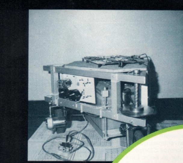
The three wheels that propel Microtron’s Stage I chassis were sourced from an electronics catalog rather than fabricated: Loofbourrow selected what the article describes as a ready-made complete built motorized wheel and fitted three identical units to the triangular aluminum frame (Interface Age, Apr. 1977). Each wheel is 4½ inches in diameter and 1 inch wide, and operates on either 6 or 12 VDC (Interface Age, Apr. 1977). The operating voltage Loofbourrow chose for the robot is 12 V, supplied by a standard automobile battery housed inside the frame (Interface Age, Apr. 1977).
The catalog-rated load figures are substantial for a wheel of that diameter. According to the article, a single wheel can carry 200 lb at walking speed on a smooth, level surface and deliver a stalled pulling force of 20 lb (Interface Age, Apr. 1977). Current consumption is rated at 2 A with no mechanical load and 8 A at stall (Interface Age, Apr. 1977). Three wheels at stall on a 12 V supply represent a potential aggregate draw of 24 A — a factor that is visible in the component sizing of the motor-control circuit described below (general context; not attributed to the article). The wheel manufacturer, catalog designation, and order number are not stated in the article and are not claimed here.
4.1.2 Arrangement on the chassis
All three wheels are motorized. The two rear wheels of the triangular chassis — one at each rear corner — are fixed in heading and supply the primary propulsive force. The front wheel, at the apex of the triangle, is also driven but serves simultaneously as the steerable element: it can be pivoted to a commanded angle by a dedicated steering motor acting through a gear reduction (Interface Age, Apr. 1977). The result is a drive arrangement in which all three wheels contribute to forward or reverse thrust while a single steerable wheel governs the turning arc of the chassis.
The steering mechanism, the gear reduction at the front wheel’s pivot, and the circuits that command steering angle are covered in Vol. 5. That volume also covers the op-amp comparator front-end that converts analog joystick and potentiometer positions into the digital signals used by both the steering and the speed-control circuits. The present volume addresses only the drive function — the supply of propulsive torque to all three wheels and the control of speed and direction.
4.2 The H-bridge
4.2.1 Diagram C: Motorized Wheel Control
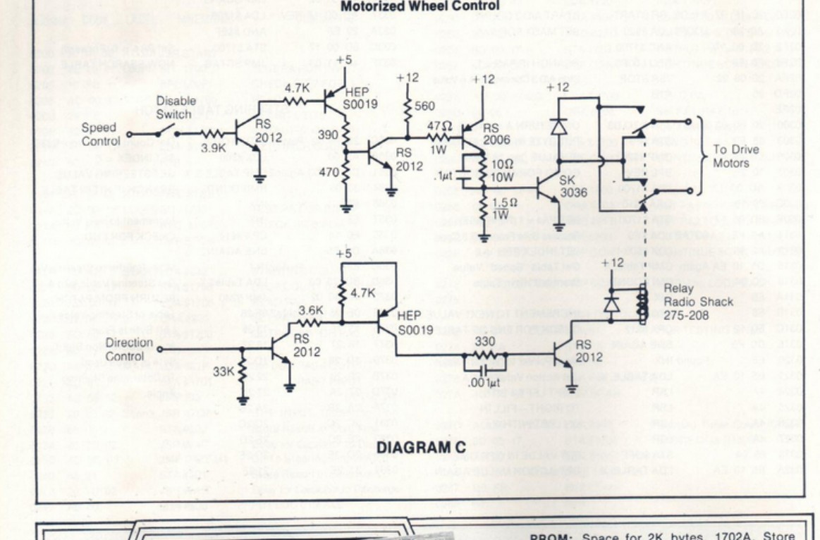
Diagram C of the Interface Age article, captioned “Motorized Wheel Control,” presents the complete motor-drive circuit for the drive wheels. The diagram is reproduced as Figure 1 above.
4.2.1.1 Component labels read from the scan
The following components are labeled in Diagram C. Part designations are transcribed as read from the scan; ambiguities are flagged where the print quality introduces a genuine reading risk.
Table 1 — Component labels read from the scan
| Component | Label as read | Reading notes |
|---|---|---|
| Small-signal transistors (multiple) | RS 2012 | Four instances across both paths; “RS” reads as a Radio Shack part prefix, consistent with the RS-labeled relay in the same diagram |
| Driver transistors (two) | HEP S0019 | One in the speed path, one in the direction path. The scan reads “S0019” with what appears to be the capital letter S; a plausible alternate reading is “50019” with the digit 5 — the letter-S reading is consistent with GE’s HEP S (small-signal) product line, but verification against a cleaner copy is advisable before citing the part number as definitive |
| Intermediate driver, speed path | RS 2006 | One instance, in the upper circuit between the HEP S0019 driver and the SK 3036 power stage; reads clearly in the scan |
| Power transistor, speed path | SK 3036 | One instance, at the output stage of the speed path; this transistor carries the drive-motor load current |
| Relay, direction path | Radio Shack 275-208 | One instance, lower right of the diagram. The scan is read here as “275-208”; “275-206” is a plausible misread of the final digit, and the relay model should be verified against a cleaner scan or against Radio Shack catalogs of the period before the number is cited as definitive |
| Resistors — speed path | 3.9 K, 4.7 K, 390 Ω, 470 Ω, 560 Ω, 47 Ω 1 W, 10 Ω 10 W, 1.5 Ω 1 W | All readable in the scan |
| Resistors — direction path | 33 K, 3.6 K, 4.7 K, 330 Ω | All readable in the scan |
| Capacitors | 0.1 μF (speed path), 0.001 μF (direction path) | Values readable |
| Supply rails | +5 V, +12 V | Both labeled at multiple points; +5 V appears at the HEP S0019 collector pull-up resistors, +12 V at the motor and relay-coil supply |
| Protection diodes | Unlabeled | Two instances: one across the relay coil (flyback protection), one in the “To Drive Motors” output path (motor back-EMF protection) |
The motor manufacturer, motor part number, and exact gear ratios of the drive wheels are not shown on Diagram C and are not stated in the article body; they are not claimed here. Current values for individual circuit nodes beyond the catalog wheel ratings given in the article are also not stated in the source and are not asserted here.
4.2.2 Circuit topology
Diagram C presents two distinct signal paths, which together constitute a hybrid relay-and-transistor motor drive.
Speed-control path (upper half of Diagram C). The “Speed Control” signal — originating in the comparator front-end covered in Vol. 5 — enters through a 3.9 K resistor. A “Disable Switch” appears in series with this input, providing a manual means of cutting propulsive power without altering the direction state. The signal drives a cascade of NPN transistor stages: RS 2012 → HEP S0019 → RS 2012 → RS 2006, terminating at the base of the SK 3036 power transistor. The SK 3036 carries the motor load current; its conduction is governed by the signal presented by the preceding stages. Passive elements in this path include coupling and biasing resistors (390 Ω, 470 Ω, 560 Ω, 47 Ω 1 W), a 0.1 μF filter capacitor, and high-power resistors (10 Ω 10 W and 1.5 Ω 1 W) in the output stage. The high-power resistors in the SK 3036 output path suggest significant current handling at that stage. A diode appears in the motor output path, providing protection against back-EMF from the motor windings. The specific biasing role of each resistor in the cascade cannot be determined with certainty from Diagram C alone and is not asserted here.
Direction-control path (lower half of Diagram C). The “Direction Control” signal enters through a 33 K resistor and drives a parallel transistor chain: RS 2012 → HEP S0019 → RS 2012. The final RS 2012 in this chain energizes the coil of the Radio Shack 275-208 relay, which is powered from the +12 V rail. A flyback diode across the relay coil protects the driving transistor from the inductive kickback of the coil when the relay de-energizes. A 330 Ω resistor and a 0.001 μF capacitor appear in the relay-driver stage.
Combined function. The relay armature contacts appear at the upper right of Diagram C, labeled “To Drive Motors.” When the relay is in one state, current passes through the drive motors in the forward direction; when energized to the opposite state, the contact arrangement reverses the polarity at the motor terminals and the motors run in reverse. The SK 3036 in the speed path remains the series element controlling current magnitude in both relay states.
This architecture — one power transistor controlling current magnitude, one relay reversing polarity — achieves the motor-reversing function of an H-bridge while using a simpler and lower-cost implementation than a full transistor bridge. The tradeoff is that a mechanical relay switches more slowly than a transistor and has a finite contact-cycle life; for a hobbyist mobile robot operating at walking speeds, neither constraint was practically significant. The characterization of this as a hybrid relay-and-transistor H-bridge is general engineering context, not attributed to the article.
4.3 Speeds
4.3.1 Five forward, five reverse
Microtron’s Stage I drive system provides five discrete forward speeds and five discrete reverse speeds (cyberneticzoo). The article documents speed selection as a software-controlled function: the KIM-1’s 6502 assembly routines command the drive circuit for controlled intervals, producing a set of discrete speed steps from a timing table rather than a continuously variable output (Interface Age, Apr. 1977). The programming model, the specific timing values, and the full speed-control assembly listing are examined in Vol. 7.
4.3.2 The analog front-end for speed
The “Speed Control” input at the left of Diagram C originates in an analog circuit that reads the position of a speed-control potentiometer. An op-amp comparator stage converts the potentiometer voltage into a digital signal that the KIM-1 can read through its port-A (PA) pins; the assembly routines then translate that pin state into the appropriate motor command. The full comparator circuit — Diagram D of the Interface Age article — is examined in Vol. 5, which covers the complete analog front-end for both speed and steering. The PA pin assignments used by the speed-control comparator output are part of the same Diagram D description and are documented in Vol. 2 (KIM-1 I/O) and Vol. 5.
Comments (0)