Loofbourrow · Volume 9
Cheatsheet — Mike / Microtron Quick Reference
9.1 At a glance
Table 1 — At a glance
| Attribute | Value | Source |
|---|---|---|
| Builder | Tod Loofbourrow, age 14 at Stage I; member, Amateur Computer Group of New Jersey | Interface Age, Apr. 1977 |
| Build span | 1975–76 | Bagnall, “Tim and Kim” |
| Names | ”Mike” (cover short form) / “Microtron” (article body) | Interface Age, Apr. 1977; cyberneticzoo |
| Final height / weight | ~6 ft / ~70 lb | Inc., 1996, via cyberneticzoo |
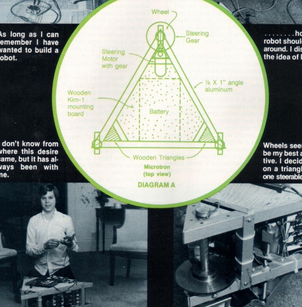
| Frame (Stage I) | Triangular, ⅛″×1″ angle aluminum, ~23″ sides | Interface Age, Apr. 1977 |
| Stage I base height | ~15″ (Interface Age) / ~14″ (cyberneticzoo) — discrepancy unresolved | Interface Age, Apr. 1977; cyberneticzoo |
| Drive | Three motorized wheels, one steerable (front apex) | Interface Age, Apr. 1977 |
| Speeds | Five forward, five reverse | cyberneticzoo |
| Steering range | 0°–60° | cyberneticzoo |
| Power | 12 V car battery | Interface Age, Apr. 1977; cyberneticzoo |
| Brain | KIM-1 — MOS 6502 @ 1 MHz, 1 KB RAM | Interface Age, Apr. 1977; Bagnall, “Tim and Kim” |
| Primary article | Interface Age, Apr. 1977, Vol. 2 No. 5 (11 pp.) | — |
| Book | How to Build a Computer-Controlled Robot, Hayden, 1978 | — |
Age-at-build conflict. Bagnall’s “Tim and Kim” chapter describes Loofbourrow as a “gifted 12-year-old hacker” (Bagnall, “Tim and Kim”); the Interface Age article, authored by Loofbourrow himself, states he was fourteen at the time of the Stage I build (Interface Age, Apr. 1977). The primary-source account is taken as authoritative throughout this series.
9.2 KIM-1 brain
Table 2 — KIM-1 brain
| Specification | Value | Source |
|---|---|---|
| Processor | MOS Technology 6502 | Bagnall, “Tim and Kim” |
| Clock | 1 MHz | Bagnall, “Tim and Kim” |
| RAM | 1 KB (1,024 bytes) — eight MOS Technology 6102 chips | Bagnall, “Tim and Kim” |
| I/O controllers | Two MOS 6530 RRIOTs (ROM + RAM + I/O + timer each) | Bagnall, “Tim and Kim” |
| Monitor | TIM (Terminal Interface Monitor), ~2 KB, in 6530 ROM | Bagnall, “Tim and Kim” |
| Display | Six-digit seven-segment LED | Bagnall, “Tim and Kim” |
| Keypad | 23 keys; includes RS (reset), GO, and SST (single step / debug) | Bagnall, “Tim and Kim” |
| Expansion | Two 44-pin edge connectors (address bus, data bus, I/O) | Bagnall, “Tim and Kim” |
| PA register address | $1700 | Interface Age, Apr. 1977, Speed Control listing |
9.3 PA pin map
9.3.1 Inputs — read by 6502 at $1700
Table 3 — Inputs — read by 6502 at $1700
| PA pin | Connector pin | Signal / function | Source |
|---|---|---|---|
| PA 5 | Pin 36 | Speed Command comparator output (Comparator A) | Interface Age, Apr. 1977, Diagram D |
| PA 7 | Pin 34 | Steering Command comparator output (Comparator B) | Interface Age, Apr. 1977, Diagram D |
| PA 6 | Pin 35 | Steering Pot comparator output (Comparator C) | Interface Age, Apr. 1977, Diagram D |
| PA 0 | Pin 2 | Filtered RC path (1 K + 0.1 µF); no comparator shown — function not labeled in diagram | Interface Age, Apr. 1977, Diagram D |
9.3.2 Outputs — driven by 6502 through 7404 hex inverter
Table 4 — Outputs — driven by 6502 through 7404 hex inverter
| PA pin | Connector pin | Signal | Drives | Source |
|---|---|---|---|---|
| PA 3 | Pin 38 | Speed Control | SK 3036 power transistor chain → drive motors | Interface Age, Apr. 1977, Diagram B |
| PA 1 | Pin 40 | Steer Left | Steering relay driver chain — left direction | Interface Age, Apr. 1977, Diagram B |
| PA 2 | Pin 39 | Steer Right | Steering relay driver chain — right direction | Interface Age, Apr. 1977, Diagram B |
PA 4 and the PB port have no documented robot use.
9.4 Drive & steering
9.4.1 Wheel specifications
Table 5 — Wheel specifications
| Attribute | Value | Source |
|---|---|---|
| Diameter | 4½″ | Interface Age, Apr. 1977 |
| Width | 1″ | Interface Age, Apr. 1977 |
| Operating voltage | 6 or 12 VDC (robot uses 12 V) | Interface Age, Apr. 1977 |
| Load rating (walking speed, smooth/level) | 200 lb | Interface Age, Apr. 1977 |
| Stall force | 20 lb | Interface Age, Apr. 1977 |
| No-load current | 2 A | Interface Age, Apr. 1977 |
| Stall current | 8 A | Interface Age, Apr. 1977 |
Circuit topology: relay-and-transistor H-bridge — one power transistor (SK 3036) controls current magnitude; one relay reverses motor polarity for direction.
9.4.2 Component part numbers
Table 6 — Component part numbers
| Component | Part number as read | Ambiguity / notes | Source |
|---|---|---|---|
| Small-signal transistors | RS 2012 | Reads clearly; four instances across drive circuit | Interface Age, Apr. 1977, Diagram C |
| Intermediate driver | RS 2006 | Reads clearly; one instance each in drive and steering circuits | Interface Age, Apr. 1977, Diagram C |
| Driver transistors | HEP S0019 | Alternate reading: 50019 (digit 5 vs. capital letter S); verify against cleaner scan before citing as definitive | Interface Age, Apr. 1977, Diagram C |
| Power transistor (drive) | SK 3036 | Reads clearly | Interface Age, Apr. 1977, Diagram C |
| Drive relay | Radio Shack 275-208 | Final digit uncertain; 275-206 is a plausible misread; verify against Radio Shack catalog of the period | Interface Age, Apr. 1977, Diagram C |
| Steering relay | Radio Shack 275-206 | Stated verbatim in the diagram’s own note (“Relay Contacts Shown For Radio Shack Relays Part #275-206”); no scanning ambiguity in this designation | Interface Age, Apr. 1977, Diagram C (steering) |
| Quad comparator | RS 339N | Reads clearly; Radio Shack part prefix consistent with other RS-designated components | Interface Age, Apr. 1977, Diagram D |
| 5 V regulators | MC 7805 (×2) | “MC” = Motorola house prefix; reads clearly; two separate regulated outputs (logic + microprocessor) | Interface Age, Apr. 1977, Diagram B |
| Hex inverter | 7404 | Reads clearly; inverts PA 1, PA 2, PA 3 outputs before motor driver chains | Interface Age, Apr. 1977, Diagram B |
9.5 Sensors (Stage II/III)
All Stage II/III sensor facts are documented by cyberneticzoo, not by the Interface Age article or the Hayden book.
Table 7 — Sensors (Stage II/III)
| Sensor | Specification | Stage | Source |
|---|---|---|---|
| Ultrasonic transducer | ~1″ to >10 ft effective range | II | cyberneticzoo |
| Impact ribbon switches | Eight, distributed around the octagonal frame perimeter | II | cyberneticzoo |
| Rubber feelers | Low-obstacle contact sensing below ultrasonic beam | II | cyberneticzoo |
| Microphone | ~10 voice commands | III | cyberneticzoo |
The Stage II frame is octagonal, ~27″ wide, ~14″ high (cyberneticzoo). Make and model of the ultrasonic transducer, sensor-to-KIM-1 wiring, and voice-recognition method are not stated in available sources and are not claimed here.
9.6 Software
All software facts from the Interface Age, Apr. 1977, listings and flowchart.
9.6.1 Routines
Table 8 — Routines
| Routine | Function | Source |
|---|---|---|
| Initialization | Sets PA data-direction register (PA 1, 2, 3 as outputs; PA 0, 5, 6, 7 as inputs); clears Speed Count; sets On Time to 0, Off Time to 0A; centers steering; clears PA; sets Bumper Cycle Count to 0. Runs once at startup. | Interface Age, Apr. 1977, Flowchart |
| Speed Control | Software PWM: reads Speed Count, tests bit 7 (On-Off indicator); on Off-cycle end loads On Time into Speed Count with bit 7 set and asserts PA 3; on On-cycle end loads Off Time into Speed Count without bit 7 and releases PA 3. Register access is read-modify-write at $1700. | Interface Age, Apr. 1977, Speed Control listing |
| Manual (joystick) Control | Main loop (entry at Scan Routine 2A): calls A/D 1, A/D 2, A/D 3 subroutines with discharge delay loops; subtracts A/D 2 from A/D 1 for three-way steering decision; tests A/D 3 against direction threshold; searches Manual Control Table; decomposes result byte into Off Time / On Time nibbles; returns to 2A. | Interface Age, Apr. 1977, Flowchart + listing |
| Manual Control Table | Address $0010; ten nibble-packed entries symmetric about a center OFF: FAST (rev) … SLOW (rev) / OFF / SLOW (fwd) … FAST (fwd); upper nibble = Off Time; lower nibble = On Time | Interface Age, Apr. 1977, Speed Control listing (Fig. 1) |
| Steering Table | Labeled “Steering Value Patch”; maps A/D 2 result to steering output byte written to PA 1 / PA 2 | Interface Age, Apr. 1977, listing p. 8 |
9.6.2 PA write masks (Speed Control)
Table 9 — PA write masks (Speed Control)
| Action | Mask | Effect on $1700 |
|---|---|---|
| Motor off (end of On cycle) | AND #$F7 (1111 0111) | Clears PA 3 (Speed Control output); preserves all other bits |
| Motor on (end of Off cycle) | OR #$08 (0000 1000) | Sets PA 3 (Speed Control output); preserves all other bits |
Table-driven design — two lookup tables plus a single shared search loop — fits the full behavioral vocabulary (five forward speeds, stop, five reverse speeds; steer left / steer right / no steer) within the KIM-1’s 1 KB RAM.
Sources
- Interface Age, Apr. 1977, Vol. 2 No. 5 — primary source; article authored by Loofbourrow; covers Stage I chassis, circuit Diagrams A–D, and 6502 assembly listings in full.
- cyberneticzoo — Stage II/III sensor suite, frame dimensions by stage, five-forward/five-reverse speed count, 0°–60° steering range, and final height/weight via Inc., 1996.
- Bagnall, Brian, “Tim and Kim” chapter, On the Edge — KIM-1 architecture, chip details, pricing ($245 fully assembled), production history, and Loofbourrow biographical background.
- daughterofkrypton — book print run (~20,000 copies).
- How to Build a Computer-Controlled Robot, Tod Loofbourrow, Hayden, 1978 — deepest primary source; covers Stage I in greater depth than the Interface Age article; Internet Archive identifier
howtobuildcomput0000loof; restricted to borrow-only lending at this writing. Designated as a planned enrichment for a future accuracy pass; not yet incorporated into this volume series.
Comments (0)