Loofbourrow · Volume 6
Sensing & Autonomy — From Joystick to Obstacle Avoidance to Voice
Introduction
Microtron’s three build stages trace a progression in autonomy that is itself a concise history of the design choices available to a hobbyist roboticist in the mid-1970s. Stage I delegated all perception to the human operator, who read the environment and transmitted intent through a joystick. Stage II moved environmental sensing onto the robot, giving it enough awareness of its surroundings to navigate and avoid obstacles without continuous human guidance. Stage III extended that awareness to the acoustic domain, allowing the robot to receive instructions by voice. The Interface Age April 1977 article documents Stage I in full — its circuit diagrams and assembly listings cover the joystick front-end and the KIM-1’s response to it. Stages II and III are documented by cyberneticzoo, which records the sensor suite and capability descriptions for each subsequent stage; those secondary-source facts are attributed accordingly throughout this volume.
6.1 Headline facts
Table 1 — Headline facts
| Attribute | Value | Source |
|---|---|---|
| Stage I control method | Joystick (operator-in-the-loop) | Interface Age, Apr. 1977 |
| Stage II sensing: ultrasonic | Range ~1 inch to over 10 feet | cyberneticzoo |
| Stage II sensing: impact switches | Eight ribbon switches, one per frame side | cyberneticzoo |
| Stage II sensing: feelers | Soft rubber feelers for low obstacles | cyberneticzoo |
| Stage II frame | Octagonal, ~27″ wide, ~14″ high; eight sides | cyberneticzoo |
| Stage III capability | Voice command recognition, ~10 oral commands | cyberneticzoo |
| Stage III transducer | Microphone | cyberneticzoo |
| Ultrasonic sensor make/model | Not stated in available sources | — |
| Sensor-to-KIM-1 wiring (Stage II/III) | Not covered in the available diagrams | — |
| Voice-recognition method | Not described in available sources | — |
| Exact Stage II/III transition dates | Not stated in available sources | — |
6.2 Stage I — Teleoperation
6.2.1 Operator as sensor
In Stage I, no sensing hardware was installed on the robot itself. All perception of the environment resided in the human operator, who observed the robot’s surroundings directly and responded by moving a joystick. The robot’s intelligence, such as it was at this stage, consisted entirely of faithfully executing the operator’s joystick commands — translating analog input into motor action with minimal latency.
This is the configuration documented in the Interface Age April 1977 article. The article covers the analog comparator front-end that reads the joystick, the relay and transistor circuits that drive the motors, and the 6502 assembly listings that bridge them. Stage I thus constitutes a closed loop in which the operator, the joystick, and the KIM-1 together form the sensing and decision system — the robot contributes only the actuation half.
6.2.2 The analog front-end as the Stage I sense organ
The comparator circuit of Diagram D — the subject of Vol. 5 — is the Stage I analog-to-digital boundary. An RS 339N quad-comparator package compares voltages from speed and steering potentiometers against reference levels and produces logic levels on the KIM-1’s port-A (PA) input pins: PA 5 (Pin 36) for speed, PA 7 (Pin 34) and PA 6 (Pin 35) for steering, and a fourth signal through PA 0 (Pin 2) via a filtered path (Interface Age, Apr. 1977, Diagram D). The comparator outputs are the only sensory data the Stage I robot receives; they encode operator intent, not environmental state. A joystick or speed-control pot that produces a voltage above the relevant comparator threshold sets the corresponding PA bit high; one that falls below leaves it low. The 6502 assembly routines poll these bits and execute the appropriate speed or steering response.
The Stage I operator-in-the-loop arrangement has a structural consequence worth noting: the assembly listings documented in the Interface Age article are designed specifically for this single-bit threshold representation of analog input. The implications for the software architecture, and the way the joystick flowchart organizes the polling and branching, are examined in Vol. 7.
The complete Stage I signal path — joystick → comparator → PA bits → 6502 → inverters → transistor chains → motors — is assembled in full in Vol. 5.
6.3 Stage II — Obstacle Avoidance
6.3.1 The octagonal frame and its sensor complement
Stage II replaced the Stage I triangular aluminum chassis with a new frame. The Stage II body is octagonal in plan and measures approximately 27 inches wide by approximately 14 inches high (cyberneticzoo). The eight-sided geometry accommodated a distributed sensor suite that gave the robot the perimeter coverage needed for autonomous navigation.
Three classes of sensor are documented for Stage II (cyberneticzoo):
- An ultrasonic transducer providing echo-ranging capability with an effective range of approximately 1 inch to over 10 feet.
- Eight impact sensors implemented as ribbon switches, mounted on the sides of the frame.
- Soft rubber feelers for detecting low-level obstacles below the ultrasonic transducer’s coverage zone.
The make and model of the ultrasonic transducer are not stated in the available sources and are not claimed here. The wiring of any of these Stage II sensors to the KIM-1 — the specific port pins, conditioning circuits, and analog-to-digital arrangements that would complete the sensor-to-processor path — is not covered in the circuit diagrams available for this deep dive. Those diagrams (Diagrams A through D in the Interface Age article) document the Stage I analog front-end; the Stage II sensor interface is not among them.
6.3.2 Ultrasonic ranging
An ultrasonic ranging transducer measures the time of flight of a sound pulse reflected from an obstacle. The transmit element emits a burst of ultrasonic energy; the receive element listens for the echo; the elapsed time, multiplied by the speed of sound and divided by two for the round-trip path, gives the distance to the reflecting surface. This operating principle is general electronics context and is not attributed to cyberneticzoo or the Interface Age article. The reported range of approximately 1 inch to over 10 feet (cyberneticzoo) characterizes the sensor’s useful working envelope on Microtron, but the transducer’s operating frequency, pulse repetition rate, and beam angle are not stated in the available sources and are not claimed here.
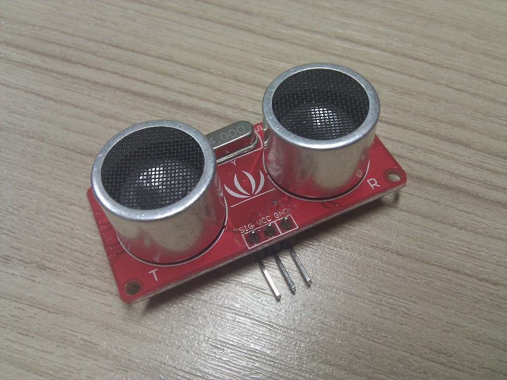
A paired-transducer arrangement — a separate transmit element and a separate receive element — is the conventional architecture for echo-ranging sensors of this type, and the HC-SR04 module shown above illustrates the component class. Whether Microtron’s 1976 ultrasonic unit used separate transducers or a single bidirectional element is not stated in the available sources and is not asserted here.
6.3.3 The eight impact ribbon switches
Eight impact sensors in the form of ribbon switches were distributed around the perimeter of the Stage II octagonal frame (cyberneticzoo). A ribbon switch is a normally-open contact that closes when pressed; mounting one on each outward-facing surface of the frame creates a tactile collision detector for each sector of the robot’s perimeter. The Stage II frame has eight sides (cyberneticzoo), and cyberneticzoo reports eight ribbon switches — one per side is a natural correspondence, though cyberneticzoo does not state explicitly that each switch maps to a specific frame panel. This pairing is noted as an observation consistent with the geometry, not a documented design specification. The mechanical mounting arrangement, connector details, and KIM-1 port assignments for the ribbon switches are not in the available circuit diagrams and are not claimed here.
6.3.4 Soft rubber feelers
The third sensing modality documented for Stage II is a set of soft rubber feelers (cyberneticzoo). These address a gap in the ultrasonic sensor’s coverage: a ranging transducer mounted at a height appropriate for detecting walls and furniture may not see objects that are low to the floor — a step, a protruding leg, or debris at ground level. Compliant contact feelers at a lower mounting height provide tactile detection for these obstacles. The mechanical form, stiffness, switching mechanism, and KIM-1 connection of the rubber feelers are not described in the available sources and are not claimed here.
6.3.5 Complementary modalities
The three Stage II sensing modalities cover distinct ranges and obstacle types. Ultrasonic ranging provides advance warning of obstacles at a distance of up to roughly ten feet, allowing the robot time to alter its heading before contact. The ribbon switches provide definitive contact detection at the perimeter when proximity data did not prevent a collision. The rubber feelers extend contact detection downward to ground-level obstacles that fall below the ultrasonic sensor’s beam. This characterization of how the three modalities complement each other is consistent with the documented capabilities and reflects general principles of sensor fusion in mobile robotics; it is not attributed as a claimed design rationale from any source.
6.4 Stage III — Voice
6.4.1 The microphone and spoken commands
Stage III added a microphone to Microtron’s sensor suite and gave the robot the ability to respond to approximately ten spoken commands (cyberneticzoo). Voice command recognition represented a qualitative shift in the human-machine interface: instead of a joystick that encoded operator intent through body position, or the operator’s role as remote environmental sensor in Stage I, Stage III allowed the operator to issue commands verbally at a distance, in natural language, from a subset of recognized words.
Cyberneticzoo documents the Stage III capability — the microphone, the approximate command count — without describing the voice-recognition implementation. The method by which spoken commands were distinguished from background noise and from one another, the signal-processing chain from microphone to recognized command, and any hardware or software elements that supported the recognition are not described in the available sources and are not claimed here. By the mid-1970s, limited speaker-dependent voice recognition was achievable with analog filter banks or template-matching circuits; whether Microtron’s Stage III implementation used such techniques is an open question the sources do not answer.
6.4.2 Stage III in context
The addition of voice recognition to a battery-powered mobile robot controlled by a 1 MHz 6502 with 1 KB of RAM is notable as a hobbyist achievement, regardless of the implementation details. Recognizing even a small vocabulary of commands reliably in an untreated acoustic environment represents a non-trivial signal-processing problem. The Interface Age article, which documents only Stage I, contains no voice-recognition circuitry or listings; Stage III’s hardware and software remain undocumented in the available primary source.
6.5 The Sense → Decide → Drive Loop
6.5.1 Qualitative structure
Across all three stages, Microtron implements the same abstract control loop: sense, decide, drive. The stages differ in where the sensing happens and how much of the deciding is delegated to the robot’s own processor.
In Stage I, the sensing resides in the operator’s eyes and brain. The operator reads the environment, decides on a motor command, and encodes that decision through the joystick. The KIM-1’s job is limited: poll the comparator outputs on the PA input pins, look up the corresponding speed and steering values from the assembly tables, and assert the appropriate PA output bits to the motor drivers. The 6502 does not evaluate obstacles; it executes operator decisions.
In Stage II, the robot itself performs the sensing. The ultrasonic transducer reports the distance to the nearest obstacle in the forward hemisphere. The ribbon switches around the frame perimeter signal contact in any of eight sectors. The rubber feelers signal ground-level contact below the sonar beam. A decision process running on the KIM-1 would need to map these inputs to motor commands — slow down, stop, reverse, turn — without an operator in the loop. The specific algorithm that performed this mapping, the PA pin assignments for the Stage II sensor inputs, and the assembly routines that replaced the Stage I joystick-polling code are not documented in the available sources. The Stage I software documented in the Interface Age listings is the basis for Vol. 7; any Stage II overlay or replacement firmware is not available for analysis.
In Stage III, the command source shifts again, from joystick to microphone. The recognized spoken command presumably maps to the same kinds of motor-command outputs that the joystick produced in Stage I — speed, heading, stop — but mediated now by a voice-recognition front-end rather than a comparator circuit. Again, the implementation is undocumented in available sources.
6.5.2 The drive and steering response
Whatever sensory input triggers a response, the execution side of the loop terminates in the same drive and steering hardware across all stages. A speed command energizes the SK 3036 power transistor chain in the drive circuit, governing current to the three motorized wheels. A steering command fires the appropriate Steer Left or Steer Right relay, reversing the steering motor’s polarity and sweeping the front wheel toward the commanded angle. The hardware that performs this output function is documented in Vols. 4 and 5; it does not change between stages — only the upstream sensing and decision logic evolves.
The implication is that any Stage II or Stage III sensing upgrade needed only to produce the same set of output signals that the Stage I joystick produced — speed and steering commands encoded in the KIM-1 port-A output bits routed through the 7404 inverters. Whether Stage II firmware reused the Stage I speed tables and steering routines from the Interface Age listings, or replaced them with new code, is not documented in the available sources and is not asserted here. That question, along with the full Stage I software architecture, is examined in Vol. 7.
Comments (0)