Loofbourrow · Volume 3
Chassis & Frame — a Triangle of Angle Aluminum
3.1 The triangular base
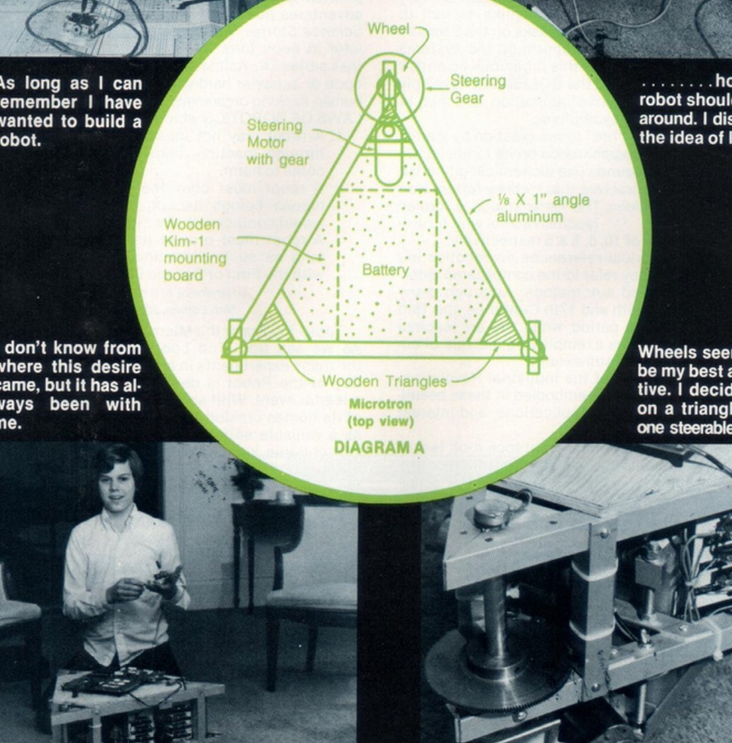
The structural skeleton of Microtron’s Stage I rolling chassis is fabricated from ⅛″×1″ angle aluminum — the dimension appears in both the article’s opening paragraph and in the label on Diagram A, which reads “⅛ X 1″ angle aluminum” (Interface Age, Apr. 1977). The frame measures approximately 23″ in width and approximately 15″ in height, as stated by Loofbourrow in the article itself (Interface Age, Apr. 1977); cyberneticzoo gives the Stage I height as approximately 14″ (cyberneticzoo). The discrepancy is unresolved; both figures are recorded and attributed throughout this volume.
Diagram A, the circular top-view schematic published with the article, establishes the chassis geometry and the placement of every major component. At the forward apex sits the single steerable Wheel, driven by a Steering Motor with gear acting through a Steering Gear. The two rear corners carry fixed drive wheels. Inside the triangle, the Wooden KIM-1 mounting board occupies the rearward section of the interior and the Battery sits at the center. Wooden Triangles reinforce the three corners (Interface Age, Apr. 1977, Diagram A). The steering motor and its gear reduction are examined in detail in Vol. 5; the rear drive wheels and their control circuit are covered in Vol. 4.
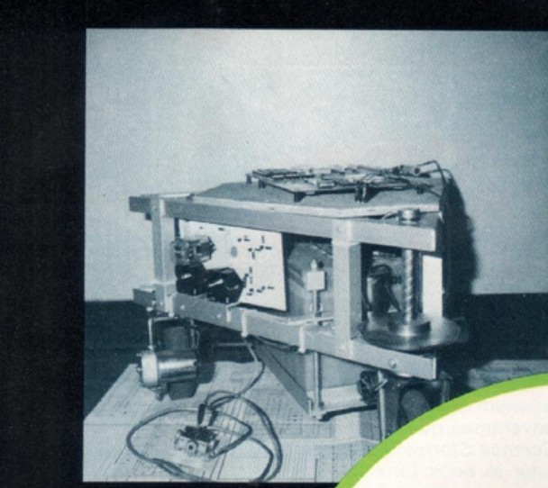
The frame is constructed as two horizontal triangular layers bolted together. Loofbourrow first laid the parts out on a full-size diagram of the frame, which he records “had to be some 20″ long,” and assembled a single triangular base with the three motorized wheels mounted — only to find the wheels “were not firmly anchored to the frame and could wobble” (Interface Age, Apr. 1977). Each wheel’s shaft passed through a hole in a circular disk, and because the holes were slightly larger than the shafts, the shafts “wobbled too freely.” The remedy was a second triangle above the first, carrying small wooden triangles in its corners through which the shafts passed: “I built this second triangle and attached it rigidly to the first with one inch angle aluminum. The shafts were then firmly mounted and, although they could still rotate, they were prevented from wobbling” (Interface Age, Apr. 1977). “The two triangles were separated from each other by five inches, and the entire framework was solidly bolted together” (Interface Age, Apr. 1977). The wooden KIM-1 mounting board and the 12 V car battery are carried inside the resulting enclosure.
The motorized wheels are documented in the article as 4½″ in diameter and 1″ wide, running on 6 or 12 VDC; their full drive specifications and load figures are examined in Vol. 4. Fastener specifications and the construction details of the tall upper body visible on the Interface Age cover are not documented in the available primary sources and are left explicitly unclaimed in this volume; the upper-body construction is left unclaimed throughout the series.
3.2 Why a triangle, one steerable wheel
Loofbourrow describes the design decisions in the article’s opening section. The first question — how the robot should move — resolved quickly: “I immediately discarded the idea of legs” (Interface Age, Apr. 1977). A sidebar on the same page records the decision in condensed form: “I discarded the idea of legs” and “Wheels seemed to be my best alternative. I decided upon a triangle with one steerable wheel” (Interface Age, Apr. 1977).
The choice of a triangle over a rectangle or square followed from geometry and economy. A triangular base requires only three wheels, one fewer than the minimum for a four-sided base. Loofbourrow records the structural reasoning directly: “After trying many designs, I finally settled on a triangle for stability and strength. A triangle also provided a good base for anything I might add and it needed one less wheel than a rectangle or a square” (Interface Age, Apr. 1977). The geometric point is that three non-collinear contact points define a plane uniquely: the chassis rests flat without rocking, independent of floor irregularities that would cause a four-point base to teeter. None of the available sources state this constraint explicitly; it is noted here as general context, not attributed to the article.
Within the triangle, one wheel is steerable and the other two are fixed. The steerable wheel sits at the apex — the forward point of the triangle — and is rotated by a dedicated motor driving through a gear reduction (Diagram A, Interface Age, Apr. 1977). “The front wheel was to be the only steerable wheel, rotated by a separate motor, while the back two wheels were locked in place” (Interface Age, Apr. 1977). With the rear wheels supplying propulsion and the front wheel commanded to a desired angle, the chassis turns in a controlled arc. The steering-motor circuit and the analog control front-end that commands the steering angle are covered in Vol. 5.
3.3 From rolling base to standing robot
The Stage I triangular chassis was the first of three documented configurations. Each stage enlarged or extended the base and added capability.
Table 1 — From rolling base to standing robot
| Stage | Footprint | Height | Source |
|---|---|---|---|
| I — Triangular rolling base | Triangular, ~23″ wide | ~15″ (Interface Age); ~14″ (cyberneticzoo) | Interface Age, Apr. 1977; cyberneticzoo |
| II — Octagonal sensor platform | Octagonal, ~27″ wide | ~14″ | cyberneticzoo |
| Final — Standing robot | — | ~6 ft (~70 lb) | Inc., 1996, via cyberneticzoo |
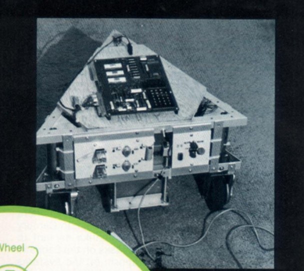
Stage I is the triangular rolling chassis documented in the Interface Age article and shown in the figures above. The article gives the height as approximately 15″ and the width as approximately 23″ (Interface Age, Apr. 1977); cyberneticzoo gives the Stage I height as approximately 14″ and the side dimension as approximately 23″ (cyberneticzoo). The height discrepancy is unresolved and both values are recorded here with their respective attributions, consistent with how Vol. 1 handles the same conflict.
Stage II replaced the triangular frame with an octagonal body measuring approximately 27″ across and approximately 14″ high (cyberneticzoo). The enlarged perimeter accommodated a suite of sensors: an ultrasonic transducer, eight impact ribbon switches distributed around the perimeter, and rubber feelers — the hardware that enabled autonomous obstacle avoidance without continuous operator input. The sensing subsystem is examined in Vol. 6.
The final configuration, as reported by Inc. magazine in 1996 (via cyberneticzoo), stood approximately six feet tall and weighed approximately seventy pounds. The construction of the tall upper body — the structure that extended the robot from a rolling base of roughly 14–15″ to a standing height of approximately six feet — is not described in the Interface Age article or in any other available primary or secondary source consulted for this series. Its construction, the date of its addition, and its structural details are left explicitly unclaimed throughout.
Comments (0)