Loofbourrow · Volume 7
Programming Model & Software — Driving a Robot in 6502 Assembly
The Interface Age article (Apr. 1977) devotes several listing pages to the 6502 assembly code that ran on the KIM-1 and controlled Microtron’s motors. Those pages present five discrete code elements — an Initialization routine, a Speed Control program, a Manual Control program, a Manual Control Table, and a Steering Table — together with a full flowchart of the joystick control loop. Taken together, these artifacts document a software design that achieves motor speed control, direction handling, and operator input processing within the KIM-1’s 1 KB of RAM. The approach is table-driven throughout, a choice that reduced instruction code at the cost of a handful of data bytes and made speed behavior modification a matter of rewriting table entries rather than patching branch chains.
7.1 The programs
7.1.1 Initialization
The Initialization routine runs once, at startup, before the main control loop begins. The Interface Age flowchart identifies its work in four consecutive setup steps. First, the port-A data-direction register is written to establish which PA lines will operate as inputs and which as outputs, consistent with the hardware assignments documented in Vols. 2 and 5: the three motor-command bits (PA 1, PA 2, PA 3) are configured as outputs; the four sensor-read bits (PA 0, PA 5, PA 6, PA 7) are configured as inputs. Second, the Speed Count variable is set to zero, the On Time variable is set to zero, and the Off Time variable is given an initial nonzero value — the flowchart labels this starting Off Time as 0A (Interface Age, Apr. 1977, Flowchart). Third, steering is centered and the PA register is cleared to all zeros, ensuring no inadvertent motor command is in effect when the main loop first runs. Fourth, the Bumper Cycle Count is set to zero. Only after all four initialization steps does control transfer to the Scan Routine, which serves as the re-entrant entry point of the main loop.
The Initialization listing in the article occupies a block of addresses in the lower region of the KIM-1’s writable RAM. Comments in the listing — readable in the article scan, page 6 — label each instruction’s purpose in plain English, identifying each variable assignment and each register store by function rather than by register number. The specific hexadecimal bytes written to the direction register and to the variable locations are not reproduced here in full; the listing is the definitive record.
7.1.2 Speed Control
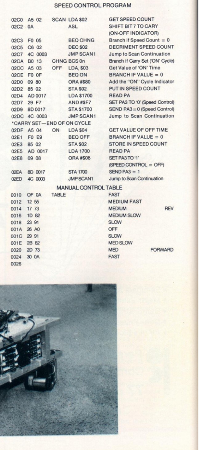
The Speed Control program implements software pulse-width modulation (PWM): rather than holding the drive motor continuously on or continuously off, it creates a repeating on/off duty cycle whose on-time and off-time durations are drawn from variables named, appropriately, On Time and Off Time. The effective motor speed is thus the ratio of on-time to off-time iterations rather than any fixed hardware setting — a technique general to 8-bit PWM in the 6502 era and not attributed exclusively to the article. Varying the ratio changes perceived speed without altering a single instruction in the Speed Control program itself; the Manual Control Table, discussed below, supplies the variation.
The routine begins each pass by loading the Speed Count variable and shifting its most significant bit — bit 7 — into the processor’s carry flag. The listing’s own comment labels bit 7 “the ON-OFF indicator”: when set, the current pass is a Motor On portion of the duty cycle; when clear, it is a Motor Off portion. This use of the carry flag to branch based on a single bit is a standard 6502 technique and is general programming context here. Based on the carry state, the routine branches to the On-cycle handler or the Off-cycle handler.
In the Off-cycle handler, On Time is read. If it is zero, the handler returns immediately to the scan continuation. If it is nonzero, the On Time value is written into Speed Count with bit 7 forcibly set (establishing the count as an On-cycle count), and the Speed Control output on PA 3 is asserted — the listing accomplishes this by reading the PA register at address $1700, applying an AND mask of #$F7 (which clears bit 3 while leaving all other bits intact), and writing the result back to the same address (Interface Age, Apr. 1977, Speed Control listing). The read-modify-write sequence preserves the steering bits in the same register.
In the On-cycle handler, Off Time is read. If it is zero, the handler branches back to the Off-cycle handler directly. If it is nonzero, Off Time is stored in Speed Count without bit 7 set (establishing an Off-cycle count), and PA 3 is released — the listing reads the PA register at $1700, applies an OR mask of #$08 (which sets bit 3 without disturbing other bits), and writes the result back (Interface Age, Apr. 1977, Speed Control listing). The comment in the listing labels this state “SPEED CONTROL = OFF.”
The combined effect is that Speed Count counts down scan iterations; when it reaches zero, the cycle switches between On and Off by reloading from the appropriate time variable. Larger On Time values mean more scan iterations with the motor on; larger Off Time values mean more iterations with it off.
7.1.3 Manual Control Program
The Manual Control program is the main loop coordinator. The article’s listing page 7 identifies it under the heading “PROGRAM FOR JOYSTICK CONTROL / ANALOG-TO-DIGITAL 2 INPUTS RELAY OUTPUTS / START PROGRAM AT LOCATION 0300 HEX” (Interface Age, Apr. 1977, p. 7). Its job is to call the three A/D conversion subroutines in sequence, use the results to decide speed and direction, look up the corresponding on-time and off-time byte in the Manual Control Table, and store those values where the Speed Control program will find them on the next pass.
The program organizes its work around three A/D subroutine calls, labeled A/D 1, A/D 2, and A/D 3 in the flowchart. A/D 1 and A/D 2 read the two steering-related comparator channels; their results are later compared to determine which steering direction to assert. A/D 3 reads the speed-and-direction channel. After the A/D 3 result is available, a threshold test divides the value range: results at or above the threshold indicate forward motion; results below it indicate reverse. A direction flag is set accordingly, and the A/D value is adjusted before proceeding to the table lookup.
The table lookup searches the Manual Control Table for the entry matching the adjusted A/D 3 result. Once the matching byte is found, it is decomposed into its two constituent nibbles: the upper four bits carry the Off Time value; the lower four bits carry the On Time value. The Off Time is isolated by shifting the byte right four times; the On Time is isolated by re-reading the original byte and masking off the upper four bits. Both results are stored in the Speed Count and timing variables consumed by the Speed Control program. This nibble-packing technique — fitting the two timing values into a single byte rather than two — saves a byte on the timing representation for each entry, at the cost of a few extra shift and mask instructions. The extraction steps are visible in both the flowchart and the listing and are central to understanding the table format.
7.1.4 Manual Control Table
The Manual Control Table is a ten-entry lookup structure whose listing begins at address 0010 in the article scan (Figure 1 above); the entry addresses step by two ($0010, $0012, $0014, …), so each entry occupies two bytes. The speed timing for an entry is held in a single nibble-packed byte — Off Time in the upper four bits, On Time in the lower four bits — which the Manual Control program recovers by a four-bit right shift and a mask. The table covers the full symmetric speed range from maximum reverse through stop to maximum forward:
Table 1 — The Manual Control Table is a ten-entry lookup structure whose listing begins at address 0010 in the article scan (Figure 1 above); the entry addresses step by two ($0010, $0012, $0014, …), so each entry occupies two bytes. The speed timing for an entry is held in a single nibble-packed byte — Off Time in the upper four bits, On Time in the lower four bits — which the Manual Control program recovers by a four-bit right shift and a mask. The table covers the full symmetric speed range from maximum reverse through stop to maximum forward
| Entry | Speed label | Direction |
|---|---|---|
| 1 | FAST | Reverse |
| 2 | MEDIUM FAST | Reverse |
| 3 | MEDIUM | Reverse |
| 4 | MEDIUM SLOW | Reverse |
| 5 | SLOW | Reverse |
| 6 | OFF | Stopped |
| 7 | SLOW | Forward |
| 8 | MED SLOW | Forward |
| 9 | MED | Forward |
| 10 | FAST | Forward |
The labels are those printed in the comment column of the listing (Interface Age, Apr. 1977). The OFF entry at position 6 is the midpoint; entries 1–5 mirror entries 7–10 in structure with reverse-direction byte values. The Manual Control program indexes this table based on the A/D 3 result and the direction flag, extracting the byte at the matching entry for nibble decomposition.
The byte values in each entry determine the actual motor duty cycle. A FAST entry’s On Time byte would be large relative to its Off Time byte (more iterations with the motor on than off), while a SLOW entry would have a smaller on-time fraction. The exact byte values are visible in Figure 1 and are not enumerated here; the figure is the authoritative record.
7.1.5 Steering Table
The Steering Table, labeled “Steering Value Patch” in the article, appears on listing page 8 alongside the Manual Control Program (Interface Age, Apr. 1977). It provides the lookup values for the steering computation: the Manual Control program searches this table using the A/D 2 result to find the appropriate steering output value, which is then written to the PA steering bits (PA 1 and PA 2). The table maps digitized pot positions to steering angles by associating each A/D count range with a pre-computed steering byte, giving the steering response a structured, repeatable set of thresholds without requiring arithmetic in the control loop. The specific entry count, byte format, and address range of the Steering Table are visible in the scan but are not transcribed here; the listing page carries the definitive values.
7.2 The joystick control flow
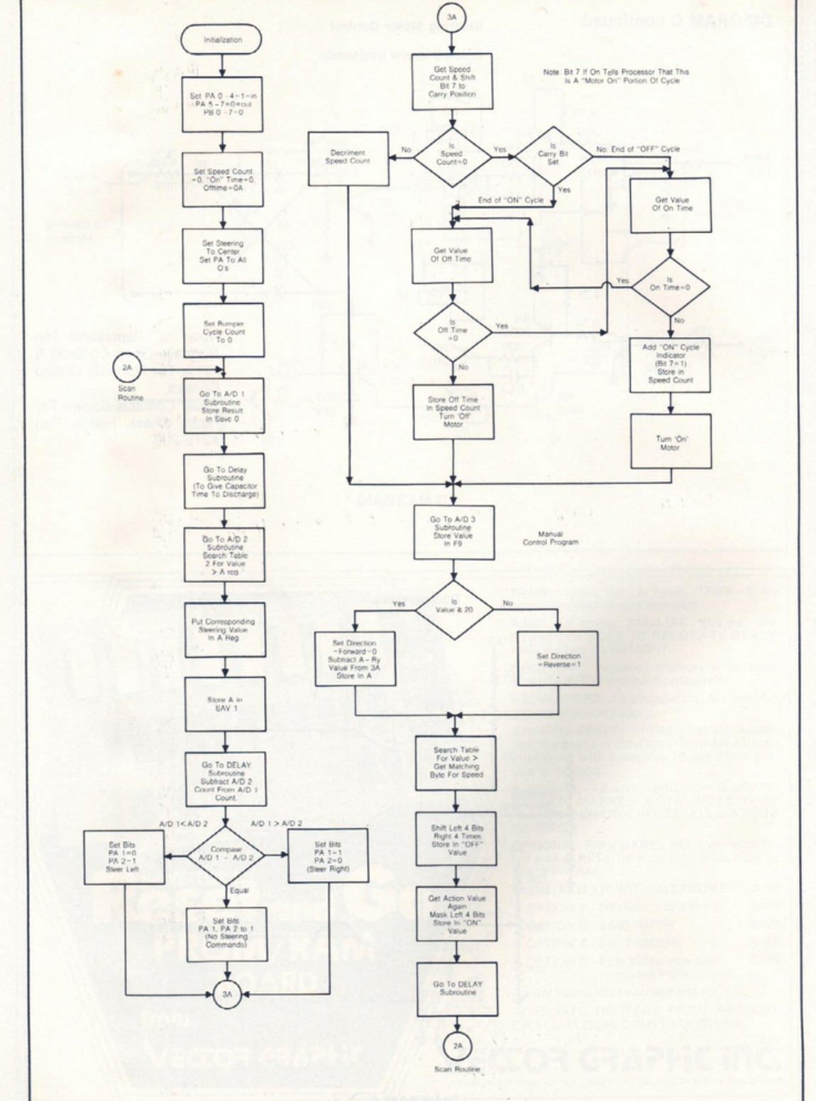
The flowchart titled “Flow Chart for Joystick Control Program” appears on page 11 of the Interface Age article (Apr. 1977) and presents the full logic of the main loop as an annotated block diagram. The structure is a single-pass loop with two re-entrant connector labels — 2A for the Scan Routine entry and 3A for the speed-and-direction section — and two sub-chains that run in parallel conceptually but are sequential in execution: a steering chain on the left and a speed-cycle chain on the right.
7.2.1 Initialization phase
The flowchart’s first block is the Initialization sequence, which executes once and does not repeat. The steps, as labeled in the flowchart boxes, are:
- Port A is configured: the data-direction register is written to set PA 0 through 4 as inputs and PA 5 through 7 in their corresponding input/output roles; PB 0 through 7 are also configured. The flowchart’s own label for this step is “Set PA 0–4 = 1-in PA 5–7 (without) PB 0–7–0” (Interface Age, Apr. 1977, Flowchart).
- Speed Count is set to zero; On Time is set to zero; Off Time is set to 0A — a small initial off-interval value (Interface Age, Apr. 1977, Flowchart).
- Steering is set to center; PA is cleared to all zeros.
- Bumper Cycle Count is set to zero.
7.2.2 Scan Routine (2A)
Following initialization, control falls through to connector 2A, which marks the top of the repeating loop. Every pass through the loop runs this sequence:
- A/D 1 subroutine. The first A/D subroutine is called; its result — a count value representing the time required for the relevant capacitor to charge through the operator’s pot resistance — is stored in Save 0. The underlying A/D technique is charge-counting: the subroutine polls a comparator output bit on PA, counting loop iterations until the bit transitions; the count is proportional to pot resistance. This is a general RC timing A/D technique common in hobbyist 8-bit systems of the era and is not attributed exclusively to the article.
- Delay subroutine (first call). A Delay subroutine runs to allow the capacitor to discharge completely before the next A/D read, ensuring that each subroutine call starts from a consistent capacitor state.
- A/D 2 subroutine and steering table search. A/D 2 is called; the Steering Table is then searched for the value matching the A/D 2 result. The corresponding steering value is placed in the accumulator register.
- Store steering value. The steering value is stored in the SAV 1 location for use in the steering comparison.
- Delay subroutine (second call) and difference computation. A second Delay subroutine call provides another discharge interval; the A/D 2 count is then subtracted from the A/D 1 count. This difference drives the steering decision.
7.2.3 Steering comparison and output
The result of the A/D 1 minus A/D 2 subtraction produces a three-way branch:
- A/D 1 < A/D 2 (negative result): PA 1 is set to 0 and PA 2 is set to 1, asserting the Steer Left command.
- A/D 1 > A/D 2 (positive result): PA 1 is set to 1 and PA 2 is set to 0, asserting the Steer Right command.
- A/D 1 = A/D 2 (zero result): PA 1 and PA 2 are both set to 1. The flowchart labels this state “No Steering Commands.”
After the steering bits are set, control passes to connector 3A, which joins the steering chain to the speed-cycle chain.
7.2.4 Speed cycle (3A)
Connector 3A picks up the speed-cycle logic, which handles the PWM duty cycle. A note in the flowchart reads: “Bit 7 if On Tells Processor That This Is A ‘Motor On’ Portion Of Cycle” (Interface Age, Apr. 1977, Flowchart). The logic proceeds as follows:
- Speed Count is loaded and bit 7 is shifted to the carry flag.
- Speed Count is decremented.
- A two-stage check examines whether Speed Count has reached zero and whether carry is set:
- Speed Count not yet zero: the cycle continues in its current phase; the flow passes directly to the Manual Control section.
- Speed Count zero, carry set (On cycle ending — “End of ON Cycle”): Off Time is read. If Off Time is zero, the branch loops back to the On cycle handler without changing state. If Off Time is nonzero, Off Time is stored in Speed Count (without bit 7), the motor is turned off, and the Manual Control section proceeds.
- Speed Count zero, carry clear (Off cycle ending — “End of OFF Cycle”): On Time is read. If On Time is zero, the branch loops to the Off cycle handler. If On Time is nonzero, the On cycle indicator (bit 7 = 1) is added to On Time and the combined value is stored in Speed Count; the motor is turned on.
7.2.5 Manual Control section and return
After the speed-cycle decisions, the flow enters the Manual Control section:
- A/D 3 subroutine is called; the result is stored.
- The result is tested against a threshold value. Values meeting or exceeding the threshold are directed to the forward path: direction is set to 0, and the working value is adjusted by subtracting a reference before the table search. Values below the threshold take the reverse path: direction is set to 1.
- The Manual Control Table is searched for the entry matching the adjusted value; the corresponding speed byte is found.
- The byte is decomposed into its two nibbles: right-shifted four times to produce the Off Time value; re-read and masked to produce the On Time value. Both are stored in the Speed Count variables for the Speed Control program.
- A final Delay subroutine call provides discharge time.
- Control returns to connector 2A — the Scan Routine — and the loop repeats.
7.3 Table-driven design
The two lookup tables — Manual Control Table for speed, Steering Table for steering — are the organizing principle of the robot’s software. Neither table is incidental to the design; both replace what would otherwise be multi-branch conditional chains executing arithmetic in the control loop. The substitution of a short table search for a longer sequence of comparisons and branches is a standard 8-bit assembly technique (general context), and in the context of a 1 KB memory budget it offers a concrete advantage: a general-purpose search loop of a few instructions, used repeatedly, costs fewer code bytes than the equivalent case-by-case branch tree. The more cases the behavior requires, the more favorable the tradeoff becomes.
7.3.1 The Manual Control Table format
The byte-packing decision in the Manual Control Table — upper nibble for Off Time, lower nibble for On Time — exemplifies the memory discipline the 1 KB constraint imposed. Storing the On Time and Off Time as two separate bytes would cost an extra byte per entry; packing both into one nibble-pair byte saves that byte across each of the ten entries. The cost is a two-step extraction on every use: right-shift four times to recover Off Time, mask the upper nibble to recover On Time. Both extraction steps are short instruction sequences, and they execute once per control loop pass — a modest overhead in exchange for the saving. Vol. 2’s discussion of the 1 KB budget places the significance of such savings in context; the point here is that the nibble-packed format is a direct response to memory pressure, not a performance optimization.
The table’s symmetric structure — five reverse speeds, a stop, five forward speeds — also reflects a design choice about behavior range. Rather than computing speed levels from A/D values arithmetically (multiplication, lookup of square roots, or similar), the program maps any A/D result to one of ten discrete outcomes. The operator’s pot thus selects among ten speeds and a stop, and the KIM-1 executes the appropriate duty cycle without any floating-point or division instruction. For a 1 MHz 6502 without a hardware multiply, this discrete-level approach is the natural one.
7.3.2 The Steering Table role
The Steering Table plays the same structural role as the Manual Control Table but for the steering channel. The A/D 2 result — a count representing how far the operator has displaced the steering pot — is compared against Steering Table entries to find the matching steering value. This insulates the steering output logic from the raw A/D count; if the comparator thresholds or capacitor values change, updating the table entries recalibrates behavior without touching any instruction in the control loop. The table search is the same pattern used for speed: compare, branch on match or continue, return the associated value.
The use of two independent lookup tables for two independent behaviors — with a single general-purpose search mechanism shared between them — is consistent with writing the minimum amount of code for the maximum behavioral coverage, which is what a 1 KB budget demands.
7.4 How software meets hardware
7.4.1 The PA register interface
The Speed Control program accesses the KIM-1’s port-A register — the 6530 RRIOT’s PA data register, mapped to address $1700 in the address space — on every pass through the speed-cycle logic. This address appears in the Speed Control listing each time a PA read or write is performed (Interface Age, Apr. 1977, Speed Control listing). The read-modify-write idiom is used throughout: load from $1700, apply a bit mask, store back to $1700. This is the correct approach when multiple independent one-bit signals share a single 8-bit register and must not interfere with each other.
The AND mask #$F7 (binary 1111 0111) clears bit 3 — PA 3, the Speed Control output — while leaving all other bits unchanged; the OR mask #$08 (binary 0000 1000) sets bit 3 while leaving all others unchanged (Interface Age, Apr. 1977, Speed Control listing). The steering output bits (PA 1 and PA 2) occupy bits 1 and 2 of the same register, and they are preserved across every speed-control write by this mask discipline. The Manual Control program uses the same register for all PA output writes.
7.4.2 Input PA pins — reading the comparators
On the input side, the four comparator-derived signals from Diagram D (documented in Vol. 5) arrive at the KIM-1 connector and are readable at the corresponding bits of the PA register at $1700. The comparator-to-PA-pin assignments — established in Vol. 2 and confirmed by Diagram D — are:
Table 2 — On the input side, the four comparator-derived signals from Diagram D (documented in Vol. 5) arrive at the KIM-1 connector and are readable at the corresponding bits of the PA register at $1700. The comparator-to-PA-pin assignments — established in Vol. 2 and confirmed by Diagram D — are
| Comparator | Operator input | PA input pin | Connector pin |
|---|---|---|---|
| A | Speed Command / Pot | PA 5 | Pin 36 |
| B | Steering Command Pot | PA 7 | Pin 34 |
| C | Steering Pot | PA 6 | Pin 35 |
| — (filtered RC path) | — | PA 0 | Pin 2 |
The A/D subroutines poll PA 5, PA 6, and PA 7 by reading from $1700 and examining the appropriate bit. Each subroutine counts polling iterations until the comparator output bit transitions, producing a digital count proportional to the operator’s pot position. PA 0’s filtered path does not involve a comparator stage; its role in the A/D subroutines, if any, is not labeled in the available diagrams and is not claimed here.
7.4.3 Output PA pins — driving the 7404
On the output side, three PA bits carry motor commands through the 7404 hex inverter (Diagram B, documented in Vol. 5) to the transistor driver chains:
Table 3 — On the output side, three PA bits carry motor commands through the 7404 hex inverter (Diagram B, documented in Vol. 5) to the transistor driver chains
| PA output pin | Connector pin | 7404 output | Motor command |
|---|---|---|---|
| PA 3 | Pin 38 | Speed Control | Drive motor on/off (duty cycle) |
| PA 1 | Pin 40 | Steer Left | Steering motor — left direction |
| PA 2 | Pin 39 | Steer Right | Steering motor — right direction |
The 7404 inverts each PA output before it reaches the base networks of the transistor chains. The AND and OR masks in the Speed Control listing — clearing or setting PA 3 — correspond to the two states of the Speed Control signal at the 7404 input; after inversion the output drives the SK 3036 power transistor that governs drive-motor current (Vol. 4). The Steer Left and Steer Right bits in the flowchart’s steering decision (PA 1 = 0/1, PA 2 = 1/0) similarly arrive at the steering relay driver chains after inversion, energizing the appropriate relay to commutate the steering motor in the selected direction (Vol. 5). The specific polarity at each transistor base — whether active-high or active-low — follows from the 7404 inversion and the circuit design in Diagrams B and C, as documented in Vols. 4 and 5.
7.4.4 The complete signal path in software terms
From the software perspective, the complete cycle is:
- The Scan Routine calls A/D subroutines that poll PA input bits, counting iterations to produce digital values representing pot positions.
- The Manual Control section tests the A/D 3 count against the direction threshold, sets a direction flag, adjusts the count, and searches the Manual Control Table for the matching speed byte.
- The speed byte’s nibbles are extracted and stored as On Time and Off Time.
- On each subsequent pass, the Speed Control program uses On Time and Off Time to toggle PA 3 via read-modify-write at $1700, creating the drive-motor duty cycle.
- The steering comparison subtracts A/D 1 from A/D 2 and writes PA 1 and PA 2 to assert or deassert the steering commands.
- After each pass the loop returns to 2A and repeats.
The entire behavioral vocabulary of Microtron — forward, reverse, five speed levels in each direction, stop, steer left, steer right, no steer — is exercised through these seven PA bits, two lookup tables, and a handful of subroutines. The total byte count of the robot program as a whole is not asserted here; the primary source does not state a definitive total in a form clearly legible in the available scan. What the article does make clear, by presenting the listings in hexadecimal alongside the mnemonics, is that the program was intended to be entered byte by byte through the KIM-1’s keypad — the hex column is exactly what the operator would have typed. Vol. 2 describes that entry process.
Comments (0)